Table of Contents
Advertisement
Advertisement
Table of Contents

Related Manuals for Citizen CBM-910 Type II


Summary of Contents for Citizen CBM-910 Type II
- Page 1 DOT MATRIX PRINTER MODEL CBM-910 Type II User’s Manual...
- Page 2 WEEE MARK...
- Page 3 CITIZEN is registered trade mark of CITIZEN WATCH CO., LTD., Japan CITIZEN es una marca registrada de CITIZEN WATCH CO., LTD., Japón ESC/POS is a trade mark of Seiko Epson Corporation. — 1 —...
-
Page 4: Declaration Of Conformity
Declaration of Conformity This printer conforms to the following Standards: Low Voltage Directive 73/23/EEC, 93/68/EEC and the EMC Directive 89/336/EEC, 92/31/EEC, 93/68/EEC. LVD : EN60950-1 EMC : EN55022 EN61000-3-2 EN61000-3-3 EN55024 This declaration is applied only for 230V model. IMPORTANT: This equipment generates, uses, and can radiate radio frequency energy and if not installed and used in accordance with the instruction manual, may cause interference to radio communications. -
Page 5: General Precautions
4. Except explained elsewhere in this manual, do not attempt to service, disassemble or repair this product by yourself. 5. Note that CITIZEN SYSTEMS shall not be responsible for any damage attributable to incorrect operation/handling or improper operating environments which are not specified in this manual. - Page 6 Please be familiar with the following precautions before reading this manual. G The following describes the degree of hazard and damage that could occur if the printer is improperly operated by ignoring the instructions indicated by the warning symbols.
- Page 7 If the printer is damaged or breaks down, be sure to turn off the power, disconnect the power plug from the wall outlet, and contact your CITIZEN SYSTEMS dealer. • Do not allow the printer to be subjected to any strong impact or shock, such as stamping, hitting, dropping, and the like.
-
Page 8: Precautions For Installation
PRECAUTIONS FOR INSTALLATION G Do not use or store the printer in a place exposed to heat of fire, moisture or direct sunlight, or in a place where the prescribed operating temperature and humidity are not met, or in a place exposed to oily mist, iron powder or dust; otherwise, the printer may get out of order, emit smoke or catch fire. -
Page 9: Precautions For Handling
G Replace the ink ribbon before it is broken by overuse. Do not refill the ink ribbon. G Leaving the printer unused for a long time with a ribbon cassette loaded may cause smudged printing. Continuous printing at low temperature may cause thin printing due to the characteristic of ink. -
Page 10: Table Of Contents
3.2 Part Descriptions ... 12 4. OPERATIONS ... 13 4.1 Connection of the AC Adapter ... 13 4.2 Setting of the Printer Cover ... 14 4.3 Setting Ribbon Cassettes ... 15 4.4 Setting Paper ... 16 4.5 Self-Printing Function ... 18 4.6 Memory Switch Setting ... - Page 11 9. CHARACTER CODE TABLE ... 47 9.1 ASCII + 910 Emulation (International) ... 47 9.2 910 Emulation (Japan) ... 47 9.3 Codepage PC437 (USA, Standard Europe) ... 48 9.4 Katakana ... 48 9.5 Codepage PC858 (Multilingual) ... 49 9.6 Codepage PC860 (Portuguese) ... 49 9.7 Codepage PC863 (Canadian-French) ...
-
Page 12: Introduction
1. INTRODUCTION The CBM-910II is a dot-impact printer widely usable with various data communication terminals and measurement terminals. This printer, being extremely compact and equipped with extensive functions, is suitable to a wide range of applications. Read this manual thoroughly to understand the product before use. -
Page 13: Type Classifications
Please use the exclusive adapter indicated below. 91AD-J (AC 100 V) 91AD-JU (AC100V, AC 120 V) 91AD-E (AC 230 V) — 9 — Printer cover A: 60 mm (Dia.) Paper roll B: 80 mm (Dia.) Paper roll Adapter 100: For AC 100 V... -
Page 14: Specifications
2.3 Specifications Item Printing method Printing direction Character configuration (W × H) (5 + 1) × 8 Number of columns per line Printing speed Character size (W × H) Character spacing Line pitch Paper feed speed Paper Interface Input buffer Emulation Code page Paper-near-end detection... -
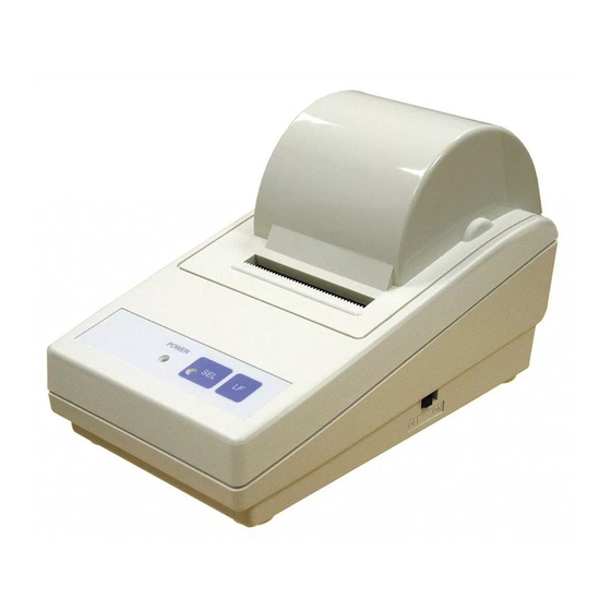
Page 15: External Appearance And Part Descriptions
3. EXTERNAL APPEARANCE AND PART DESCRIPTIONS 3.1 External Appearance (8) Print cover Upper cover Lower cover (3) Power lamp (4) SEL lamp (2) Power switch (6) SEL switch (5) LF switch (1) DC jack (7) Interface connector — 11 —... -
Page 16: Part Descriptions
Printer lights up in Select (ON LINE) state, and is put off in Deselect (OFF LINE) state. Printing operation is available only while this lamp is lit. -
Page 17: Operations
4.1 Connection of the AC Adapter (1) Ensure that the power switch is OFF. (2) Insert the output plug of the AC adapter into the DC jack of the printer. (3) Insert the power plug of the AC adapter into a power outlet supplying the designated voltage. -
Page 18: Setting Of The Printer Cover
4.2 Setting of the Printer Cover (1) Hold the protruding section at the rear of the printer cover and lift in the direction indicated. (2) Attach the cover by pressing downward after hooking the cover to the acceptor located in the front part. -
Page 19: Setting Ribbon Cassettes
4.3 Setting Ribbon Cassettes (1) Remove the printer cover turning OFF the printer. (2) Press down on the Ribbon cassette while inserting the ribbon between the printing head and the platen. (3) Wind up the ribbon slack by turning the knob in the direction of the arrow. -
Page 20: Setting Paper
(4) Insert paper into the slot of the printer mechanism. (5) Following turning-on of the power switch, as pressing the LF switch, take out printing paper by 5 to 6 cm from the printer mechanism. As passing the paper through paper outlet, mount the printer cover. - Page 21 SPECIAL REMARKS CONCERNING PAPER SHAPE: The beginning of winding (end part of the inside diameter) should satisfy the following (Refer to Drawing A): 1. Free of fold and well aligned to inside diameter 2. Free of flaps 3. Not adhered to core part (if there is one) The beginning of winding Drawing A Not accepted...
-
Page 22: Self-Printing Function
On completion of test printing, the printer enters the standby state awaiting print data. (2) Hexadecimal dump mode Turn the printer power on with the LF switch and SEL switch pressed and held. The printer prints Hexadecimal Dump characters and then prints all data sent from the host in hexadecimal code. -
Page 23: Memory Switch Setting
Change by manual operation Turn the printer power on with DIP switch No. 4 set to ON and by pressing and holding the SEL switch. The printer prints the information on the current memory switch setting and then enters the Change Setting mode. - Page 24 <Contents of Memory Switch Setting> In square brackets ([ ]), choose one of the options for each setting item. Item marked * is the default setting. Country (Selecting international character set) [*USA, FRA, GER, U.K, DEN, SWE, ITA, SPE, JPN] Selects a international character set.
-
Page 25: Paper-Near-End, Mechanical Alarm, Memory Error
POWER lamp and SEL lamp to blink simultaneously at 1/10-second intervals. This error is an unrecoverable error. Turn the equipment power off and contact your CITIZEN SYSTEMS dealer. (4) Memory switch setting error This error is developed when any abnormality is detected in the setting of memory switch when the equipment is powered on. -
Page 26: General Remarks
(3) Be careful not to drop foreign substances, such as a clip and a pin into the equipment. Otherwise, equipment failure may result. (4) To operate the printer, be sure that the printer is placed on a flat stable place. If the table is not flat or stable, the printer may be displaced by vibrations during printing, resulting in a possible danger. -
Page 27: Parallel Interface
5.1 Specifications (1) Data input system: 8 bit parallel (DATA 1-8). (2) Control signal: STB, ACK, BUSY, P.N.E., SELECT, RESET (3) Compatible connector: Printer side: 57LE-40360 (ANPHENOL or equivalent) Cable side: 57-30360 (ANPHENOL or equivalent) 5.2 Connector Pin Assignment Signal Name... -
Page 28: Description Of Input/Output Signals
• ACK . . . 8 bit data signal for requesting data. ACK is issued at the end of the BUSY signal (negative logic) • BUSY . . . Signal indicating the printer is busy. Input new data when the signal is in “LOW” condition (positive logic) •... -
Page 29: Electrical Characteristics
< HOST SIDE > DATA RESET OUTPUT SIGNAL ACK BUSY P.N.E. HCMOS Level “HIGH” level: 4.0 V MIN “LOW” level: 1.0 V MAX < PRINTER SIDE > 3.3k (HC04 or equivalent) 3.3k (HC04 or equivalent) 3.3k (HC04 or equivalent) 3.3k (HC04 or equivalent) —... -
Page 30: Serial Interface
6. SERIAL INTERFACE 6.1 Specifications (1) Synchronization: Asynchronous (2) Baud rate 1200, 2400, 4800, 9600, 19200 Baud/sec (User selection) (3) Word configuration • Start bit: 1 bit • Data bit: 7 bits or 8 bits (User selection) • Parity bit: odd, even, no parity (User selection) •... -
Page 31: Connector Pin Assignment
In addition, changing the internal resistance allows selection of pin 23/pin 25. In Factory setting, pin 23 (TTL Reset) is set. Note: 1. Signals for RS-232C are based on EIA RS-232C level. Applicable connector (D-sub connector) Printer side: 17LE-13250 (Anphenol or equivalent) Cable side: 17JE-23250 (Anphenol or equivalent) Signal Direction Host-Printer... -
Page 32: Description Of Input/Output Signal
BUSY (mark) will cause an overrun error to occur. Data can be provided to the input buffer even if the printer is printing. Busy state may also occur when power is applied, or during test printing, on-line, or when the printer is reset. -
Page 33: Electrical Characteristics
6.4 Electrical Characteristics (1) RS-232C I/O signals (RD/TD/DTR) • Input (RD) Mark = (−8 V): Stop bit Space = (+8 V): Start bit • Output (TD, DTR) Mark = (−8 V): For Busy Space = (+8 V): For Ready 2: TD 20: DTR 3: RD 25: RESET... -
Page 34: Error Detection
6.5 Error Detection Communication error • Parity error Parity error occurs when parity check is specified and parity is not observed in the even and odd parity checks. • Framing error When space state detected on detection of stop bit. •... -
Page 35: Dip Switch Setting
*1: A difference is developed by the emulation set by the memory switch. *2: After setting DIP switch No. 4 to ON, turning the printer power on with the SEL switch pressed and held causes the printer to enter the Manual memory switch setting mode. With normal power on operation, bit length setting is active. -
Page 36: Parallel Interface Type
*: Difference may occur in accordance with the emulation set by the memory switch. After setting DIP switch No. 4 to ON, turning the printer power on with the SEL switch pressed and held causes the printer enter the Manual memory switch setting mode. -
Page 37: Print Control Function
8. PRINT CONTROL FUNCTION 8.1 List of Control Codes Code Symbol (Hexadecimal) ESC + “B” 1B, 42 ESC + “R” 1B, 52 ESC + “t” 1B, 74 ESC + “/” 1B, 2F ESC + “! ” 1B, 21 ESC + “&” 1B, 26 ESC + “%”... -
Page 38: Control Code Details
8.2 Control Code Details (1) Command for Line Feed After Printing (CR/LF) By entering CR (0DH)/LF (0AH) codes, data in the print buffer is printed followed by a line feed. Without data in the print buffer, only a line feed is performed. This command is ignored just after buffer full in case of 910 emulation. - Page 39 Laterally enlarged letter assignment (SO/RS) command: With SO (0EH)/RS (1EH) codes input in any columns, the data following are printed in prints enlarged double in width. Although standard and enlarged letters can be mixed within one line, automatic (buffer-full) printing takes place when the number of columns reaches 24 (or 40) counted in standard letters.
- Page 40 Content of the input buffer, however, is held unchanged. (6) Power Down Function (DC2, DC3) Only when 3110 emulation is selected In order to reduce power consumption when printer is waiting for the operation, 2 power down modes triggered by the codes DC2 and DC3 are incorporated into this product.
- Page 41 Denmark (DEM) With n other than those specified, the set value for the U.S. is assigned. Note: At the printer power on or after RESET is applied, this setting differs depending on the status of memory switch setting. (9) Codepage Select (ESC + “t” + n) Command By the entry of ESC (1BH) + ”t”...
- Page 42 (10) Sentence Registration (ESC + “/” + n) Command With input of ESC (1BH) + “/” (2FH) + n + ‘registered sentence’ code, 24 (40)-bytes data following n are registered. Set a numeral of 1~8 to n. With any other numeral having been set, data following are regarded as normal printing data, where no registration takes place and printing conducted.
- Page 43 <Registered State> It is pen <Printing Result> Is this a pen ? It is a pen (Printed out with ESC + “!” + 1) (12) Character Registration (ESC + “&”) Command For 24-column model (ESC + “&” + A1 + A2) Individual patterns can be registered by entering the code ESC (1BH) + ”&”...
- Page 44 [Method of data transmission] d-1) Single character registration Select the address to be defined (character code) from among 20H to FFH and designate is as A1. When registering a single character, starting and ending addresses match each other. That is, A1=A2. <Example>...
- Page 45 For 40-column model In 910 emulation (ESC + “&” + C1 + A1 + A2) In 3110 emulation (ESC + “&” + A1 + A2) With ESC (1BH) + ”&” (26H) + {C1} + A1 + A2 code and the pattern data following input, a pattern is registered.
- Page 46 In 3110 emulation As this printer takes half-dot printing system, dots cannot be aligned continuously in printing (horizontal) direction. Therefore, even if any pattern is specified at point “*” at the right of point “G” above, it cannot be registered as a pattern.
- Page 47 (13) Registered Letter Valid/Invalid (ESC + “%” + n) Command Whether a registered pattern is valid or invalid is set with ESC (1BH) + ”%” (25H) + n code being input. n = 1 (01H): Registered pattern to be made valid. (Addresses for which no registration change has been conducted are taken as inside fixed characters.) n = 0 (00H): Registered pattern to be made invalid.
- Page 48 In case that assignment has been made out of the assignable range or n2 = n3 = 0 has been assigned, Bit Image mode is cancelled and Text mode starts. With this printer, on completion of read-in of 4-dot-line data or on completion of n1/n2/n3 assigning data, lacking data are printed as spaces.
- Page 49 (15) ×4 Enlarged Letter Assignment (FS + “W” + 1) Command FS (1CH) + “W” (57H) + 1 (01H) code input, ×4 enlarged letters are assigned. Data following this code are printed vertically and laterally twice enlarged. (16) ×4 Enlargement Cancel (FS + “W” + 0) Command With FS (1CH) + “W”...
- Page 50 Entering this code allows the contents of the memory switch shown in the table below to be changed. When the printer receives this code, it enters the BUSY mode. After writing to memory switch, reset is carried out and the receive buffer/ print buffer is cleared and the initial value is restored and then the contents of the memory switch is reloaded.
-
Page 51: Character Code Table
9. CHARACTER CODE TABLE 9.1 ASCII + 910 Emulation (International) 9.2 910 Emulation (Japan) — 47 —... -
Page 52: Codepage Pc437 (Usa, Standard Europe)
9.3 Codepage PC437 (USA, Standard Europe) 9.4 Katakana — 48 —... -
Page 53: Codepage Pc858 (Multilingual)
9.5 Codepage PC858 (Multilingual) 9.6 Codepage PC860 (Portuguese) — 49 —... -
Page 54: Codepage Pc863 (Canadian-French)
9.7 Codepage PC863 (Canadian-French) 9.8 Codepage PC865 (Nordic) — 50 —... -
Page 55: Codepage Pc852 (Eastern Europe)
9.9 Codepage PC852 (Eastern Europe) 9.10 Codepage PC866 (Russian) — 51 —... -
Page 56: Codepage Pc857 (Turkish)
9.11 Codepage PC857 (Turkish) 9.12 Codepage WPC1252 (Windows Latin1) — 52 —... -
Page 57: Codepage Pc864 (Arabic)
9.13 Codepage PC864 (Arabic) 9.14 Codepage PC869 (Greek) — 53 —... -
Page 58: International Character Code Table
9.15 International Character Code Table — 54 —... -
Page 59: External Dimensions
10. EXTERNAL DIMENSIONS — 55 —... - Page 60 — 56 —...
- Page 61 — 57 —...
- Page 62 1.13E-0801 Printed in Japan...