Table of Contents
Advertisement
Advertisement
Table of Contents

Summary of Contents for Humminbird TCR 101
- Page 2 Please carefully consider the following before installing your transducer. TRANSDUCER MOUNTING OPTIONS A. Transom Mount- The Humminbird high speed transducer allows the transducer element to be mounted below the bottom of the boat hull keeping the transducer out of turbulent water and...
- Page 3 B. Inside Hull Mount- The high speed transducer can be mounted inside the hull (without pivot assembly) using the proper two-part epoxy, such as Humminbird’s epoxy kit. Even though there is some loss of signal in shooting through the hull, your LCR will perform well with this type of installation.
- Page 4 Once the location is determined mark and drill three 7/64” dia.. holes noted on the template. Attach the metal bracket using three #10 self threading screws supplied. Be sure to align holes in the center of the Bracket slots. On some aluminum boats it may be necessary to use a wood back-up plate. It is important to use a silicone sealant between the screwhead and bracket in order to prevent leaking.
- Page 5 NOTE: On boats with more than 15 degree deadrise angle it may be necessary to mount the transducer slightly off parallel with the water level. (See Figure E) Mark and drill the three 9/64” dia. holes as shown on the template. Attach the metal bracket using the three #10 self threading screws supplied.
- Page 6 Step 4 TRANSDUCER ASSEMBLY- Insert the transducer assembly into the metal bracket from the bottom. Push up until the holes in the plastic pivot align with the uppermost holes in the bracket. Slide the O-ring on to the headed pin and insert it through the two parts. Assemble by screwing the ¼”x3/8”...
- Page 7 Techsonic Industries, Inc. will not be responsible for any damage due to the mounting of your transducer in this manner. NOTE: An Epoxy Kit (Part N. EPK) is available from Humminbird. This Epoxy Kit has been formulated for Inside Hull Transducer Installation.
- Page 8 Position the swivel base and drill four ¼” diameter holes. Note: The LCR hole pattern Is the same as for all Humminbird flasher units. Use hardware provided to mount this base to the boat. Next place the gimbal bracket on the swivel base and attach with four small machine screws, provided.
- Page 9 Install the mounting knobs and tighten snugly. The unit can now be swiveled and tilted to any desired position.
- Page 10 INSTALLING THE CABLES Your LCR comes equipped with Humminbird’s new Angle-Lock power and transducer connectors. The power connector is identified with the letter P on the back of the plug.
- Page 11 It plugs into the outlet on the back of the unit marked “Power”. The transducer connector is identified with the letter T and plugs into the outlet on the back of the unit marked “Transducer”. Note: An adapter (AD-4) is available to allow use of an old waterproof (BNC) transducer with the LCR, but be sure that the transducer is a 16degree.
-
Page 12: Total Screen Update
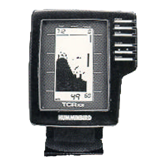
Of course, the best way to learn to read your TCR 101 is to use it, especially in familiar locations. If you know what’s underwater and can see it displayed on the screen, then you’re on your way to... -
Page 14: Operating
If you’re learning to operate the TCR 101 with its simulator, follow the directions listed “Built-In Simulator” on Page 17, and then come back to this page. If you’re learning t use your TCR 101 using actual, on-the-water readings, proceed with the following instructions. - Page 15 Select System: The TCR 101 Select System command an amazing number of functions with only four buttons: Select, Up and Down arrows, and ON/Off. When you press the Select button, each function appears in a block on the screen with easy-to-understand instructions for using the function.
- Page 16 Automatic setting: off When zoom is activated by pressing On/Off, it creates a “window” of expanded, up-close information. This window is marked by a cursor at the right of the screen and can be moved up or down with the arrow buttons. The exact depths of the upper and lower limits of the window are displayed as depth scales while you are in zoom.


