Table of Contents
Advertisement
Advertisement
Table of Contents

Related Manuals for Humminbird 400TX


Summary of Contents for Humminbird 400TX
- Page 2 Customer Support section. INSTALLATION OVERVIEW Your Humminbird fishfinder consists of two primary components to install: the control head and the transducer. The control head contains the sonar transmit and receive circuitry, as well as the user controls and display.
- Page 3 INSTALLATION PREPARATION Determining How to Mount the Transducer Your Humminbird fishfinder includes a standard transducer. This transducer can be mounted on the transom of the boat or bonded to the inside of a fiberglass hull boat. The transom installation, which is the most widely used, places the transducer on the outside of the boat hull.
- Page 4 ALTERNATE MOUNTING METHODS ALTERNATE TRANSDUCERS AND MOUNTING METHODS Your Humminbird fishfinder comes with everything necessary for installation and operation on most boats. However, there are several situations which may require a different type of transducer. Inboard boats, wood or metal hulls, and sail boats create unique transducer mounting needs Alternate transducers and mounting methods are detailed below.
- Page 5 BEGINNING INSTALLATION Now that you have determined the transducer mounting method you can begin installation of your new Humminbird fishfinder. The installation guide included on the next few pages provides detailed step by step instructions for installation of the control head and transducer. For transom mount transducer installations you will need the mounting template included with your manual.
- Page 6 Do not begin this transducer installation until you read the Installation Preparation in the Operation Guide. This chapter contains information critical to the correct installation of your transducer. Due to the wide variety of boat hulls, only general instructions are presented in the installation guide.
- Page 7 If the propeller(s) is (are) forward of the transom, it may be impossible to find an area clear from turbulence, and a different mounting technique or transducer type should be considered. Step Two - Drill the Mounting Holes 1. Remove the mounting template from the front of the Operations Manual. 2.
- Page 9 Step Four - Mount the Transducer to the Transom 1. Apply silicone sealant to the mounting holes drilled into the transom. 2. Align the transducer assembly with the drilled holes in the transom (Figure 8). 3. Use either a flat head screwdriver, a 5/16" (8mm) hex driver, or a 5/16" (8mm) socket to mount the assembly.
- Page 10 mounting bracket. Drill this hole and install the screw after final testing and adjustments have been completed.
- Page 11 If the cable is too short, extension cables are available to extend the transducer cable up to a total of 50' (15 m). Call Humminbird Customer Support for more information. Follow these steps to route the cable through the transom: 1.
- Page 12 Inside the hull mounting generally produces good results in single thickness fiberglass-hulled boats. Humminbird cannot guarantee depth performance when transmitting and receiving through the hull of the boat since some signal loss occurs. The amount of loss depends on hull construction and thickness, and the installation.
- Page 13 The transducer cannot transmit through air. The water purges any air from between the transducer and the hull and fills any voids in the coarse fiberglass surface.
- Page 14 3. Power up the Control Head. 4. Run the boat at various speeds and water depths while observing the screen on the Control Head. If the unit functions well at low speeds but begins to skip or miss the bottom at higher speeds, the transducer needs to be moved. If depth performance is required, test the fishfinder in water at the desired depth.
- Page 15 CONTROL HEAD INSTALLATION Step One - Determine Where to Mount Begin the installation by determining where to mount the control head. Consider the following to determine best location: The cables for power, transducer and temp/speed accessories (if applicable) should be installed first and must reach the mounting location. Extension cables are available.
- Page 16 fuse in the connection. If you must wire the control head directly to a battery, be sure to install an inline fuse holder...
- Page 17 (not included) for the protection of the unit (Figure 21). Humminbird is not responsible for over voltage or over current failures. In order to minimize the potential for interference with other marine electronics a separate power source (such as a second battery) may be necessary.
- Page 18 Optional: If the cables pass outside the mounting bracket, install the hole cover over the hole and fasten in place using the two #8 x 7/8” (22mm) wood screws (Figure 24).
- Page 19 5. Install the control head by sliding it onto the mounting bracket until it is fully seated. To remove the unit simply depress the latch on the rear of the unit and lift (Figure 29). Your Humminbird is now ready for operation. INSTALLATION CONTROL HEAD INSTALLATION...
- Page 20 Note: it is often necessary to make several incremental transducer adjustments before optimum high-speed performance is achieved. Important: For Transom Mount transducer installations, install the third mounting screw after the final transducer adjustments. Humminbird 3 Humminbird Lane Eufaula, Alabama 36027...
- Page 21 Wide Side transducer. When in simulator operation, the 400TX responds to control inputs as if it is in actual operation, so feel free to experiment, or to customize the unit for your particular operation.
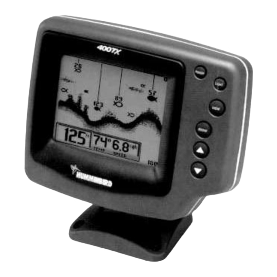
- Page 22 What You See On-Screen Your 400TX uses a 160 x 160 matrix FSTN LCD display. This display provides outstanding viewability in all light conditions over a wide range of temperatures. At initial power-up, the 400TX uses settings that were set at the factory. After initial use, the 400TX will remember the settings you enter.
- Page 23 The best way to learn to interpret structure is to operate the 400TX over a variety of known conditions and experiment with user functions to best represent those conditions on-screen.
- Page 24 The backlight is very effective for low-light and nighttime operation. When the backlight is on, the 400TX will consume more power than with the backlight off. This is important when using the 400TX in a portable configuration powered by a separate battery, or when powering the unit from a trolling motor battery.
- Page 25 The Chart View, shows only the digital depth readout, leaving more screen area for fish location and bottom depiction. If a Wide Side transducer is being used (see Using Alternative Transducers), the VIEW button is used to select one of four views available: Both, Left, Right, and Down. You can select "side" simulator to view this presentation even if a Wide Side transducer is not connected.
- Page 26 The 400TX automatically adjusts the depth range depending on the depth of the water. The unit tries to maintain the bottom depiction about 2/3 down the total range (for example, in 20' (6m) of water, the 0-30' (0-10m) range would be selected).
- Page 27 To return to automatic Depth Range control, press the MENU button until the Depth Range menu appears on-screen and use the UP ARROW to select AUTO. Zoom. The 400TX uses a greatly enhanced Zoom capability called "TruZoom" which offers expanded information on a select area of sonar information.
- Page 28 The 400TX shows Zoom range in conjunction with the full depth range. The Zoom range is shown on the left side of the screen and full range information is shown on the right side of the display. The area which is being enlarged by Zoom is indicated by the square box.
- Page 29 400TX is operated from a battery source, the voltage number can be used to determine battery life. The 400TX will operate at voltages from 10 to 20 VDC. Voltages in excess of 20 or less than 10 VDC cause the unit to power off. The Triplog resets at power off.
- Page 30 Contrast. The Contrast function allows the user to control the level of contrast of the LCD display. The 400TX will automatically adjust the display contrast to compensate for changing ambient temperatures;...
- Page 31 Selecting ID Off also disables the fish alarm. ID+ On enables the 400TX to interpret the raw sonar data and, using a variety of techniques, depict appropriate target returns as one of three different size fish symbols. Further identification shows which beam the fish is detected in.
- Page 32 Often a transducer switch is used to connect two tri-beam transducers, or a tri-beam and a wide side to the 400TX. In "Auto" the 400TX identifies the transducer as the switch is changed. Only if the transducer is faulty do you need to manually identify the transducer in the menu.
- Page 33 Reset. With the many User Options available to customize the 400TX, it is easy to configure the unit in such a way that it is detrimental to a particular use. By using the Reset function, all variable or user-controlled features of the 400TX are returned to the factory settings.
- Page 34 Sonar Beams. The second Diagnostic screen provides valuable information about the sonar function of the 400TX. The three columns of information show the raw sonar signal as it is seen by the unit.
- Page 35 The Wide Side transducer can be connectedly directly to the 400TX or used in conjunction with the standard transducer through a transducer switch. When used with a switch in conjunction with the Tri-...