Table of Contents
Advertisement
Advertisement
Table of Contents

Related Manuals for Humminbird NS25


Summary of Contents for Humminbird NS25
- Page 2 Units will typically read deeper in fresh water than in salt water. After spending a few minutes with your NS25 on the water, you will see the unit’s ability to accurately portray the underwater terrain, suspended targets, GPS position, and your position on a map.
- Page 3 GPS “Y” cable for NMEA output and GPS receiver input Publication kit In-dash mounting kit It is recommended that you install the NS25 components in the following order; 1) GPS receiver, 2) transducer, 3) card reader, then 4) control head. GPS Receiver Installation To optimize performance of the GPS receiver, mount it in an area that has full exposure to the sky.
- Page 4 Under Location Access with Deck More Than 3/8” Follow these steps to deck mount the GPS receiver routing the cable down through a thick deck: 1. Determine the best location, then route the 20 foot cable from control head to the mounting location.
- Page 5 5. Preassemble the flange, mounting bolt, and gasket with the GPS receiver, routing cable through all components; tighten GPS receiver until its base is in contact with the gasket. 6. Secure flange with #8 x 5/8 flat head screws. To access all screws you will need to rotate the GPS receiver.
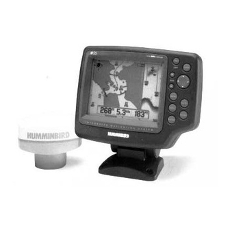
- Page 6 Customer Support section. INSTALLATION OVERVIEW Your Humminbird fishfinder consists of two primary components to install: the control head and the transducer. The control head contains the sonar transmit and receive circuitry, as well as the user controls and display.
- Page 7 INSTALLATION PREPARATION Determining How to Mount the Transducer Your Humminbird fishfinder includes a standard transducer. This transducer can be mounted on the transom of the boat or bonded to the inside of a fiberglass hull boat. The transom installation, which is the most widely used, places the transducer on the outside of the boat hull.
- Page 8 ALTERNATE MOUNTING METHODS ALTERNATE TRANSDUCERS AND MOUNTING METHODS Your Humminbird fishfinder comes with everything necessary for installation and operation on most boats. However, there are several situations which may require a different type of transducer. Inboard boats, wood or metal hulls, and sail boats create unique transducer mounting needs Alternate transducers and mounting methods are detailed below.
- Page 9 BEGINNING INSTALLATION Now that you have determined the transducer mounting method you can begin installation of your new Humminbird fishfinder. The installation guide included on the next few pages provides detailed step by step instructions for installation of the control head and transducer. For transom mount transducer installations you will need the mounting template included with your manual.
- Page 10 Do not begin this transducer installation until you read the Installation Preparation in the Operation Guide. This chapter contains information critical to the correct installation of your transducer. Due to the wide variety of boat hulls, only general instructions are presented in the installation guide.
- Page 11 If the propeller(s) is (are) forward of the transom, it may be impossible to find an area clear from turbulence, and a different mounting technique or transducer type should be considered. Step Two - Drill the Mounting Holes 1. Remove the mounting template from the front of the Operations Manual. 2.
- Page 13 Step Four - Mount the Transducer to the Transom 1. Apply silicone sealant to the mounting holes drilled into the transom. 2. Align the transducer assembly with the drilled holes in the transom (Figure 8). 3. Use either a flat head screwdriver, a 5/16" (8mm) hex driver, or a 5/16" (8mm) socket to mount the assembly.
- Page 14 mounting bracket. Drill this hole and install the screw after final testing and adjustments have been completed.
- Page 15 If the cable is too short, extension cables are available to extend the transducer cable up to a total of 50' (15 m). Call Humminbird Customer Support for more information. Follow these steps to route the cable through the transom: 1.
- Page 16 Inside the hull mounting generally produces good results in single thickness fiberglass-hulled boats. Humminbird cannot guarantee depth performance when transmitting and receiving through the hull of the boat since some signal loss occurs. The amount of loss depends on hull construction and thickness, and the installation.
- Page 17 The transducer cannot transmit through air. The water purges any air from between the transducer and the hull and fills any voids in the coarse fiberglass surface.
- Page 18 3. Power up the Control Head. 4. Run the boat at various speeds and water depths while observing the screen on the Control Head. If the unit functions well at low speeds but begins to skip or miss the bottom at higher speeds, the transducer needs to be moved. If depth performance is required, test the fishfinder in water at the desired depth.
- Page 19 CONTROL HEAD INSTALLATION Step One - Determine Where to Mount Begin the installation by determining where to mount the control head. Consider the following to determine best location: The cables for power, transducer and temp/speed accessories (if applicable) should be installed first and must reach the mounting location. Extension cables are available.
- Page 20 fuse in the connection. If you must wire the control head directly to a battery, be sure to install an inline fuse holder...
- Page 21 (not included) for the protection of the unit (Figure 21). Humminbird is not responsible for over voltage or over current failures. In order to minimize the potential for interference with other marine electronics a separate power source (such as a second battery) may be necessary.
- Page 22 Optional: If the cables pass outside the mounting bracket, install the hole cover over the hole and fasten in place using the two #8 x 7/8” (22mm) wood screws (Figure 24).
- Page 23 5. Install the control head by sliding it onto the mounting bracket until it is fully seated. To remove the unit simply depress the latch on the rear of the unit and lift (Figure 29). Your Humminbird is now ready for operation. INSTALLATION CONTROL HEAD INSTALLATION...
- Page 24 Note: it is often necessary to make several incremental transducer adjustments before optimum high-speed performance is achieved. Important: For Transom Mount transducer installations, install the third mounting screw after the final transducer adjustments. Humminbird 3 Humminbird Lane Eufaula, Alabama 36027...
- Page 25 Card Reader Installation The card reader has two mounting options. You may mount it on a vertical or horizontal flat surface, or you may mount it in-dash in a dry area. The card reader is not waterproof. Take this into consideration and follow these steps for surface and in-dash mounting.
- Page 26 The NS25 cannot recognize a C-Card if it is not properly placed in the card reader. To place a C- Card in your card reader, gently insert it face up with the gold plating facing downward. The C- Card and the slots on the card reader are keyed for correct insertion.
- Page 27 CAUTION: Some boats have 24 or 36-volt electric systems. Be sure your NS25 is connected to a 12 VDC power supply. If you must wire the NS25 directly to a battery, be sure to use the in-line fuse holder and 1.5-amp fuse provided for the protection of the unit. Hummingbird is not responsible for over-voltage or over-current failures.
- Page 28 Drilling the Mounting Holes After you have determined the best mounting location for your control head, proceed with the following instructions: 1. Depress the latch on the rear of the unit and separate the unit from the mounting bracket. 2. Set the mounting bracket on the mounting surface. 3.
- Page 29 NOTE: If the cables must pass through the mounting surface at a different location, drill the 1” hole at that location and pass the cables through from underneath. Also, you must break out the wire slots on the rear of the mounting base using needle-nosed pliers. 6.
- Page 30 5. Install the control head by sliding it onto the mounting bracket until it is fully seated. Then unit should snap into place. (To remove the unit, simply depress the latch on the ear of the unit and lift.) Your NS25 unit is now ready for operation. Testing The Installation GPS Testing Check System Status screen to confirm the unit is picking up satellite signals (shown in Satellite Status box).
- Page 31 Start-Up The NS25 is completely automatic and easy to use. Simply press the POWER button and select Start-Up. This mode determines your position and displays it on a map, tracks the bottom from 2 feet to 1000 feet displaying structure and suspended fish, and works at speeds from 0 to over 70 mph.
- Page 32 Simulator Operation The NS25 contains a Simulator mode that allows you to use the unit as if you are on the water and learn how to operate many of the features. The Simulator location is in a detailed area of the built-in map.
- Page 33 Button Functions The NS25 has 10 buttons to control all unit functions. Buttons are used for navigation options and entering data. See the following illustration and descriptive table listing buttons and functionality. Power/Light: Turns on the unit initially. Pressing and holding the Power button for three seconds turns unit off.
- Page 34 (see “User Customization” for detailed information). North-Up View The North-Up view is the initial view once the NS25 has determined its position. Your present position is always in the center of the view, with the map in the background. As your position changes, the map scrolls in the background to keep your present position in the center of the screen and to track the course history trail.
- Page 35 If the course projection deviates more than 10 degrees, the map redraws your new course at the top of the screen. If you are not moving, the NS25 cannot determine a course and will show the map oriented to the north.
- Page 36 Sonar View The Sonar view graphically depicts all sonar targets below the water surface, such as fish and structure. New sonar information appears on the right side of the graphic area and moves to the left as new information is gathered. Fish ID+ represents sonar targets detected as fish symbols with a depth.
- Page 37 System Status View The system Status view provides detailed information about the performance of the NS25. This view will appear after start-up if a position is not acquired. This allows you to monitor the status of the NS25 as it acquires satellites and determines your position.
- Page 38 You may store up to 250 permanent waypoints and 50 temporary waypoints. Permanent waypoints are retained in permanent memory; temporary waypoints are not and will be lost when the NS25 is turned off. Several options for creating waypoints are available with the NS25.
- Page 39 Interacting with On-Screen Information Using the Cursor in Map and Sonar Views The cursor is a cross-hair line visible in the graphics area and has several important functions such as selecting on-screen options, panning the map, and determining a position. The simplest and most frequent use of the cursor is to determine the distance and bearing from your present position to some point of interest.
- Page 40 Zoom +/- Around Cursor Location for More Map Detail The Zoom +/- feature controls the range viewed on the map around the cursor position. Press Zoom = to reduce the range of the map. Press Zoom – to increase the range. When adjusting the Zoom feature, a box displays in the graphics area indicating the size of the new range.
- Page 41 Extremely detailed information is available for objects and areas built into the C-Map cartography. Icons appear on the maps displaying the locations of lights, buoys, and other man made features, as well as natural areas such as tideways, current zones and sea bottom conditions. Moving the cursor to an object on the C-Map, and pressing INFO displays information about that object.
- Page 42 Customizing the Display The NS25 has customization features for selecting specific information you want to display on- screen, such as place names, depth contours, spot soundings, numeric infoboxes, etc. In any of the views, you may press the INFO button to set the information Priority Level, Customize Numeric Information, and Assign Information Priority Levels.
- Page 43 Depth – Numeric depth of water directly beneath the boat Speed Over Ground – Speed of boat, derived from GPS Course Over Ground – Direction you are traveling measured in degrees from north Coordinate Position – Present position in units selected in the Set-Up menu Time/Date –...
- Page 44 Cross Track Error (XTE) – Distance between your present position and intended route of travel. Course Made Good (CMG) – Bearing from starting waypoint to present position. Speed Of Advance (SOA) – Speed along intended route. Bearing (BRG) – Direction to a waypoint expressed in degrees relative to north. Time To Go (TTG) –...
- Page 45 Route option on the Main Menu Bar (See “Using the Menu System – Routes” for more information). The NS25 stores 10 temporary routes (lost at Power Off), and 20 permanent routes, with up to 50 waypoints in each route.
- Page 46 Note: The NS25 does not route your navigation around land, you must do so manually. Creating a Route Using CURSOR + GOTO Using the cursor and GOTO button is the quickest way to create a route. Moving the Cursor to a...
- Page 47 Using the Routes Menu You can create and travel permanent routes through the options in the Routes menu. See “Using the Menu System – Routes” section for more information. On-screen Navigation Information When traveling a route additional infoboxes appear at the bottom of the screen to provide navigation information to the destination waypoint.
- Page 48 Flag symbols mark each waypoint in the route. “S” designates the starting waypoint, and each following waypoint is marked with a number showing the sequence. The final waypoint is designated with an “E”. Selecting a View for Navigation When traveling a route, navigation information appears on the North-Up, Course-Up, Combo, Sonar and Numeric Views.
- Page 49 The Course-Up view orients the map with the direction of travel at the top of the screen. This is useful during navigation as the map and course projection line movement closely relate to corrections made to the boat’s course. When used at the more detailed map ranges, the proximity of the course projection line to the track line indicates how accurately the course is being followed.
- Page 50 Waypoint Sequencing as you move beyond a destination waypoint within the route, the NS25 automatically “sequences” to the next waypoint providing new navigation information. At times, the NS25 may not be able to determine when to automatically sequence to the next waypoint. When this occurs, a menu displays to permit manual sequencing.
- Page 51 Note: If you have not identified a destination, pressing GOTO gives you options to Enter Numeric Coordinates, Use the Cursor, Select a Waypoint from the Waypoint List, or go to the Last P-Stor Position. After selecting the waypoint, the “GO TO” options to modify route menu displays for chanding the route.
- Page 52 A waypoint is a specific location, such as a buoy or wwreck, that you may want to return to in your navigation. The NS25 stores up to 250 permanent waypoints and 50 temporary (lost at power off) waypoints. The waypoint menus allow you to navigate to watpoints, and list, create, change or delete waypoint information.
- Page 53 6. The Save Waypoint menu displays. Select Yes to save to permanent waypoint list. Select No to cancel and enter information again. Note: The NS25 will assign a system number to a new waypoint. This number is not always in the sequence in which it was created.
- Page 54 3. The Change Longitude menu displays. Scroll through digits to make changes, if needed. Select OK when finished. 4. The Change Name menu displays. Scroll through letters to make changes, if needed. Select OK when finished. 5. The Change Symbol menu displays. Scroll through symbols to make changes, if needed. Select OK when finished.
- Page 55 (Select Skip if you do not wish to name the route). 4. Select Redo to recreate the route or Yes to save it. Note: The NS25 assigns a system number to a new route. This number is not always in the sequence in which it was created.
- Page 56 The current setting for the alarm displays in the upper right corner of the alarm menu. The NS25 alarms are: Off-Course Alarm: sounds when Cross Track Error (XTE) exceeds alarm setting. Off course alarm only functions when traveling a route.
- Page 57 4. The Adjust Off Course menu displays. Scroll to a setting from .01NM to 1NM. Note: the alarm setting is saved immediately. To set Arrival Alarm 1. Highlight Arrival Alarm 2. Select ON to activate the alarm. The factory setting is .1NM. 3.
- Page 58 Note: the alarm setting is saved immediately. Set-Up The NS25 allows you to customize many features to work best for a particular use. The unit remembers these settings after power is disconnected. Listed below are descriptions and steps for Set-Up options.
- Page 59 Time Time determines the format in which the current time will display, i.e., UTC or Local. To set Time: 1. Highlight Time. 2. Select UTC, or Local. The factory setting is UTC. If Local is selected, select Set Local to set the clock.
- Page 60 North Reference determines the course and bearing calculations, relative to true magnetic north. To set North Reference: 1. Highlight North Reference. 2. Select True or Magnetic. The factory setting is True. Map Datum Map Datum selects the geodetic datum for drawing the map. CAUTION: This setting must match the datum used to create the map.
- Page 61 2. Select an interval ranging from 1-15 seconds. The factory setting is 5 seconds. Note: The larger the interval, the more distance you can cover with the course history trail. Assign IPL’s (information Priority Levels) Assign IPL’s sets the priorities for objects drawn on-screen. See “Views- Customizing the Display”...
- Page 62 To set Depth Offset: 1. Highlight Depth Offset. 2. Select a setting ranging from –10 to +10 to adjust the depth difference. The factory setting is Map Offset Map Offset accommodates localized regions where there is a present offset in the map with respect to your present position.
- Page 63 Reset Unit Reset Unit restores all features to factory settings. To Reset Unit: 1. Highlight Reset Unit. 2. Select Yes to reset all user features to original settings. Delete All Waypoints Delete All Waypoints deletes all waypoints and routes stored in memory. To Delete All Waypoints: 1.
- Page 64 The red wire is used for signal and the black wire is used for ground. The NS25 should be set at a baud rate of 4800 or 9600 (default), whichever is compatible with your Differential Beacon Receiver. This setting is made in the Set-Up menu (see “Using the Menu”...
- Page 65 Electroluminescent (EL) Mounting Quick Disconnect or In-Dash Construction High Impact Polycarbonate with Silicone Gasket Dimensions 7.5/8 “ h x 7 7/8” w x 4 3/8” d GPS Receiver Channels 12 Parallel Antenna Type Passive Patch Cable Length 20 feet (included) Mounting Socket 1”...
- Page 66 Communication NMEA V2.0 Output Only Sentences Supported: APB, BWR DGPS Input: RS-232, RTCM SC104 Data format. 4800/9600 Baud (Magellan DBR, CSI MBX-2) Memory Waypoints 250 Permanent, 50 Temporary Routes 20 Permanent, 10 temporary Course History 1000 Points Power Voltage Input 10 –...
- Page 67 CURSOR Cross-hair line in map views used to interact with on-screen information. COURSE HISTORY A course history line is shown in the graphics area, attached to the present indicator. This shows the history for your course, or where you have been. It shows the history for your course, or where you have been.
- Page 68 POWER Press POWER once to turn on the NS25. To turn it off, hold down the key for three seconds, until the audible chirp is heard. This will prevent accidentally turning the unit off during normal operation.
- Page 69 ROUTE A series of waypoints stored for navigating to a specific location. TD’s Time differentials from Loran stations. Selects position readout in Universal Transverse Mercator, the coordinate system used by some maps (such as USGS topographic maps). WAYPOINT A point of interest stored and included in routes. Cross Track Error.