
Related Manuals for Hoshizaki HNC-120AA-L


Summary of Contents for Hoshizaki HNC-120AA-L
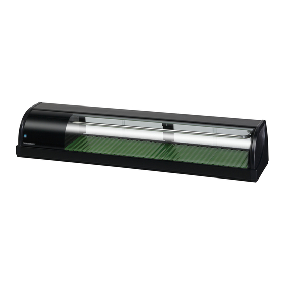
- Page 1 COUNTER SHOWCASE MODEL SERVICE MANUAL HOSHIZAKI HNC-120AA-L/R HNC-150AA-L/R HNC-180AA-L/R HNC-210AA-L/R 74NA-574 ISSUED: AUG. 10, 2001 REVISED:...
-
Page 2: Table Of Contents
1. SAFETY INSTRUCTIONS ------------------------------------------------------------------------- 1 2. MODEL NAME --------------------------------------------------------------------------------------- 3 3. OPERATING INSTRUCTIONS -------------------------------------------------------------------- 4 4. SPECIFICATIONS ---------------------------------------------------------------------------------- 5 5. DIMENSIONS ---------------------------------------------------------------------------------------- 6 [a] HNC-120AA-L ----------------------------------------------------------------------------------- 6 [b] HNC-120AA-R ----------------------------------------------------------------------------------- 7 [c] HNC-150AA-L ----------------------------------------------------------------------------------- 8 [d] HNC-150AA-R ----------------------------------------------------------------------------------- 9 [e] HNC-180AA-L ---------------------------------------------------------------------------------- 10... -
Page 3: Safety Instructions
1. SAFETY INSTRUCTIONS The following instructions contain important safety precautions and should be strictly observed. The terms used here are defined as follows: WARNING: There is a possibility of death or serious injury for the service person and a third party or the user due to improper service operations or defects in serviced products. - Page 4 5. Keep the following in mind when making electrical connections: (1) Check for proper grounding connections, and repair if necessary to prevent electric shocks. (2) Always use service parts intended for the applicable model for replacement of defective parts. Use proper tools to secure the wiring. Otherwise abnormal operation or trouble may occur and cause electric leaks or fire.
-
Page 5: Model Name
2. MODEL NAME High Grade Counter Showcase Width (cm) 120, 150, 180, 210 Unit on right 74NA5740108 H NC - 120 A A - R/L Unit Location R: Unit on right L: Unit on left HA model Development Order Starts from A Unit on left... -
Page 6: Operating Instructions
3. OPERATING INSTRUCTIONS Hoshizaki Counter Showcase is intended for temporary food display. Constructed with much glass, this showcase gives relatively insufficient heat insulation and poor cooling performance compared with refrigerators in general. For safe and efficient operation, be sure to follow the instructions below. -
Page 7: Specifications
* The pull down time and saturation temperature were measured 20 mm above the food mount (normal position) located at the interior bottom center. * The food temperature is controllable by turning over the food mounts. 74NA5740108 HNC-120AA-L HNC-150AA-L 1 Phase 115V 60Hz 0.47kVA (4.7A) -
Page 8: Dimensions
5. DIMENSIONS [a] HNC-120AA-L 74NA5740108... -
Page 9: [B] Hnc-120Aa-R
[b] HNC-120AA-R 74NA5740108... -
Page 10: [C] Hnc-150Aa-L
[c] HNC-150AA-L 74NA5740108... -
Page 11: [D] Hnc-150Aa-R
[d] HNC-150AA-R 74NA5740108... -
Page 12: [E] Hnc-180Aa-L
[e] HNC-180AA-L 74NA5740108... -
Page 13: [F] Hnc-180Aa-R
[f] HNC-180AA-R 74NA5740108... -
Page 14: [G] Hnc-210Aa-L
[g] HNC-210AA-L 74NA5740108... -
Page 15: [H] Hnc-210Aa-R
[h] HNC-210AA-R 74NA5740108... -
Page 16: Refrigeration Circuit
6. REFRIGERATION CIRCUIT Expansion Drier Valve Evaporator Fan Motor (Upper) Condenser Evaporator (Lower) Compressor Heat Exchange Refrigerant: R134a 74NA5740108... -
Page 17: Wiring Diagram
7. WIRING DIAGRAM 74NA5740108 Power Supply 1 phase 115V 60Hz Compressor Start Relay Start Capacitor Overload Relay Fan Motor Ground Fault Circuit Interrupter... -
Page 18: Construction
8. CONSTRUCTION Food Mount Sliding Door Center Frame Holder - Evaporator Pipe Top Cover Evaporator Pipe Side Frame Front Glass Cover - Unit Unit Side Cover Louver Ground Fault Circuit Interrupter Control Box 74NA5740108... -
Page 19: Removal And Replacement
9. REMOVAL AND REPLACEMENT 1. Be sure to unplug the showcase before removing or replacing the parts. 2. Handle the glass parts with care. [a] SIDE COVER Remove the Cap from the Side Cover, the machine screw inside and the two machine screws (black) at the bottom. -
Page 20: [E] Side Frame
[e] SIDE FRAME Remove the Sliding Door, Side Cover and Top Cover. Unbind the wiring on the Side Frame. Remove the two screws securing the Top Frame and the top of the Side Frame. Lift the Side Frame off the bottom fit. [f] CENTER FRAME (Except HNC-120 type) Remove the two flat head machine screws (black) securing the Center Frame to the rear... -
Page 21: [I] Unit
[i] UNIT Remove the Sliding Door, Side Cover, Top Cover, Cover - Unit and Side Frame. Take off the Compressor Terminal Cover and remove the Starter and Motor Protector. Uninsulate the Expansion Valve and unbraze the Inlet or Outlet Pipe with a gas burner (see “11. CONSTANT PRESSURE EXPANSION VALVE AND REFRIGERANT CHARGE”). -
Page 22: Refrigerant Service Information
10. REFRIGERANT SERVICE INFORMATION 1) Allowable Compressor Opening Time and Prevention of Lubricant Mixture [R134a] The compressor must not be opened more than 30 minutes in replacement or service. Do not mix lubricants of different compressors even if both are charged with R134a, except when they uses the same lubricant. -
Page 23: Constant Pressure Expansion Valve And Refrigerant Charge
8) Refrigerant Leak Check Refrigerant leaks can be detected by charging the unit with a little refrigerant, raising the pressure with nitrogen and using an electric detector. Do not use air or oxygen instead of nitrogen for this purpose, or rise in pressure as well as in temperature may cause R134a to suddenly react with oxygen and explode. -
Page 24: [D] Replacement
[d] REPLACEMENT Always protect the valve body by using a damp cloth to prevent the valve from overheating. Do not braze with the valve body exceeding 230°F (110°C). Always install a new Drier every time the sealed refrigeration system is opened. Do not replace the Drier until after all other repairs or replacement have been made. -
Page 25: Service Diagnosis
12. SERVICE DIAGNOSIS PROBLEM [1] Showcase will not start. [2] Poor cooling performance [3] Dry foods [4] Frosting 74NA5740108 POSSIBLE CAUSE 1. Ground Fault Cirucit Interrupter in OFF position. 2. Unplugged. 3. Supply voltage too low. 4. No power supply to the wall outlet. (Breaker or fuse blown out.) 5. - Page 26 HOSHIZAKI AMERICA, INC. 618 HIGHWAY 74 SOUTH, PEACHTREE CITY, GEORGIA 30269 U.S.A. PHONE: 770-487-2331 HOSHIZAKI ELECTRIC CO., LTD. 3-16 MINAMIYAKATA, SAKAE, TOYOAKE, AICHI 470-1194 JAPAN PHONE: 0562-97-2111...