
Related Manuals for Hoshizaki HNC-120BE-R-BLH


Summary of Contents for Hoshizaki HNC-120BE-R-BLH
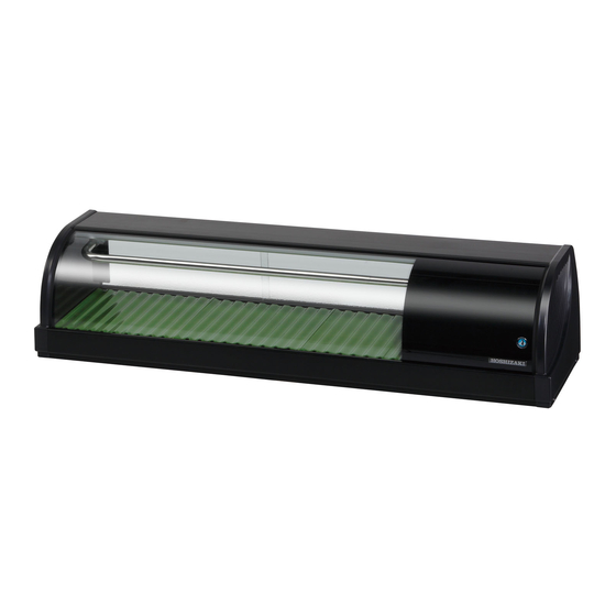
- Page 1 COUNTER SHOWCASE HNC-120BE-L/R-BLH HNC-150BE-L/R-BLH HNC-180BE-L/R-BLH HNC-210BE-L/R-BLH HNC-120BE-L/R-BH HNC-150BE-L/R-BH SERVICE MANUAL HNC-180BE-L/R-BH HNC-210BE-L/R-BH S051-1106 (051421)
-
Page 2: Table Of Contents
IMPORTANT This manual should be read carefully before the appliance is serviced. Read the warnings and guidelines contained in this manual carefully as they provide essential information for the continued safe use, service, and maintenance of the appliance. Retain this manual for any further reference that may be necessary. -
Page 3: Important Safety Information
Important Safety Information Throughout this manual, notices appear to bring your attention to situations which could result in death, serious injury, damage to the appliance, or damage to property. Indicates a hazardous situation that, if not avoided, will DANGER result in death or serious injury. Indique un risque imminent qui causera la mort ou de DANGER graves blessures, s’il n’est pas évité. - Page 4 WARNING The appliance should be destined only to the use for which it has been expressly conceived. Any other use should be considered improper and therefore dangerous. The manufacturer cannot be held responsible for injury or damage resulting from improper, incorrect, and unreasonable use.
- Page 5 WARNING, continued • Open and close the doors with care. Opening the doors too quickly or forcefully may cause injury or damage to the appliance or surrounding equipment. • Do not use combustible spray or place volatile or flammable substances in or near the appliance.
-
Page 6: Construction And Refrigeration Circuit Diagram
I. Construction and Refrigeration Circuit Diagram A. Model Name HNC - 120 B E - L/R - B L H H: Hydrocarbon refrigerant Counter Showcase L: LED Width (cm) 120, 150, 180, 210 Exterior B: Black plastic Development Order Starts from A Unit Location HE Model L: Unit on left... -
Page 7: Construction
B. Construction Air Inlet Sliding Glass Door Slider LED Switch (Only for BLH models) Air Outlet Nameplate Drain Pipe Power Switch Machine Compartment (Earth Leakage Circuit Breaker) Louver, Air Filter Power Cord Hose Joint Food Mount Thermometer* Evaporator Plug** Note: * The thermometer shows the maximum interior temperature. -
Page 8: Refrigeration Circuit Diagram
C. Refrigeration Circuit Diagram Expansion Drier Valve Evaporator Fan Motor (Upper) Condenser Evaporator (Lower) Compressor Heat Exchanger Refrigerant: R600a... -
Page 9: Operating Instructions And Service Diagnosis
II. Operating Instructions and Service Diagnosis A. Operating Instructions IMPORTANT Hoshizaki Counter Showcase is intended for temporary food display. Constructed with glass, this showcase gives relatively insufficient heat insulation and poor cooling performance compared with refrigerators in general. For safe and efficient operation, be sure to follow the instructions below. -
Page 10: Service Diagnosis
B. Service Diagnosis PROBLEM POSSIBLE CAUSE REMEDEY [1] Showcase will not 1. Power switch (earth leakage circuit 1. Turn ON. start. breaker) in OFF position. 2. Unplugged. 2. Plug in. 3. Supply voltage too low. 3. Plug into a properly earthed, independent wall outlet of 220 - 240V ±... -
Page 11: Refrigeration Circuit And Component Service Information
III. Refrigeration Circuit and Component Service Information DANGER Risk of Fire or Explosion Flammable Refrigerant Used • Follow handling instructions carefully in compliance with national or local regulations. • Do not use mechanical devices to defrost. • Do not puncture refrigerant tubing. Risk of fire or explosion due to puncture of refrigerant tubing;... -
Page 12: Refrigeration Circuit Service Information (R600A)
A. Refrigeration Circuit Service Information (R600a) WARNING • Repairs requiring the refrigeration circuit to be opened must be performed by properly trained service personnel. • Use an electronic leak detector or soap bubbles to check for leaks. Add a trace of refrigerant to the system (if using an electronic leak detector), and then raise the pressure using nitrogen gas 1 MPa. - Page 13 2. Brazing DANGER Risk of Fire or Explosion Flammable Refrigerant Used • Servicing shall be done by factory authorized service personnel to minimize the risk of possible ignition due to incorrect parts or improper service. WARNING • Wear appropriate personal protective equipment (PPE) when servicing the appliance. •...
- Page 14 3. Evacuation 1) Attach a vacuum pump to the system. Be sure to connect the charging hoses to both high and low-side refrigerant piercing valves. IMPORTANT The vacuum level and vacuum pump may be the same as those for current refrigerants. However, the rubber hose and gauge manifold to be used for evacuation and refrigerant charge should be exclusively for POE oils.
- Page 15 12) Use a combustible gas leak detector or soap bubbles to check for leaks again. 13) Place red sleeves over the process tubes. 14) Plug the appliance back into the electrical outlet.
-
Page 16: Component Service Information
B. Component Service Information WARNING • Be sure to move the power switch (earth leakage circuit breaker) to the “OFF” position, then unplug the showcase before removing or replacing the parts. • Handle the glass parts with care. Top Cover 1. - Page 17 5. Center Frame (Except HNC-120 Type) Remove the two flat head machine screws (black) securing the center frame to the rear and the two machine screws securing the center frame to the top frame. Tilt the center frame and release it from the joint.
-
Page 18: Constant Pressure Expansion Valve
C. Constant Pressure Expansion Valve IMPORTANT Follow the instructions in “DANGER” and “WARNING” for flammable refrigerant use and “III. A. Refrigeration Circuit Service Information”. 1. Specifications Model: HYP2-5VHD-1 Manufacturer: Fuji Koki Part Number: P04945-01 Refrigerant: R600a Adjustment Range: 0.01 - 0.29MPaG Pressure Rise by Adjusting Screw: 0.039 - 0.049MPa/tum 2. - Page 19 4. Replacement NOTICE Always protect the valve body by using a damp cloth to prevent the valve from overheating. Do not braze with the valve body exceeding 110°C. IMPORTANT Always install a new drier every time the sealed refrigeration system is opened. Do not replace the drier until after all other repairs or replacement have been made.
-
Page 20: Preparing The Appliance For Periods Of Non-Use
IV. Preparing the Appliance for Periods of Non-Use When shutting down the appliance for more than one week, follow the instructions below. WARNING When preparing the appliance for long storage, prevent the doors from closing to reduce the risk of children getting injured. NOTICE When preparing the appliance for long storage, clean the appliance. -
Page 21: Disposal
V. Disposal DANGER Risk of Fire or Explosion Flammable Refrigerant Used • Follow handling instructions carefully in compliance with national or local regulations. • Do not puncture refrigerant tubing. Risk of fire or explosion due to puncture of refrigerant tubing; follow handling instructions carefully. •... -
Page 22: Technical Information
VI. Technical Information A. Dimensions/Specifications 1. HNC-120BE-L-BLH... - Page 23 2. HNC-150BE-L-BLH...
- Page 24 3. HNC-180BE-L-BLH...
- Page 25 4. HNC-210BE-L-BLH...
- Page 26 5. HNC-120BE-R-BLH...
- Page 27 6. HNC-150BE-R-BLH...
- Page 28 7. HNC-180BE-R-BLH...
- Page 29 8. HNC-210BE-R-BLH...
- Page 30 9. HNC-120BE-L-BH...
- Page 31 10. HNC-150BE-L-BH...
- Page 32 11. HNC-180BE-L-BH...
- Page 33 12. HNC-210BE-L-BH...
- Page 34 13. HNC-120BE-R-BH...
- Page 35 14. HNC-150BE-R-BH...
- Page 36 15. HNC-180BE-R-BH...
- Page 37 16. HNC-210BE-R-BH...
-
Page 38: Wiring Diagram
B. Wiring Diagram HNC-***BE-L/R-BLH (with LED lighting) HNC-***BE-L/R-BH - BROWN - BLACK DBU - DARK BLUE LBU - LIGHT BLUE - WHITE - VIOLET - GRAY GR/Y - GREEN/YELLOW * The circuit enclosed in the dotted line is for the models with LED lighting. Earth Leakage Circuit Breaker Start Relay Compressor...