Table of Contents
Advertisement
Quick Links
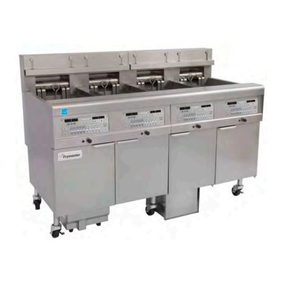
FilterQuick
Electric Fryer
Service Manual
This manual is updated as new information and models are released. Visit our website for the latest manual.
FOR YOUR SAFETY
Do Not Store or use gasoline or other
flammable vapors and liquids in the vicinity
of this or any other appliance.
FQE30
™
*8197110*
Part Number: FRY_SM_8197110 09/2017
Original Instructions
Advertisement
Table of Contents
Troubleshooting

Related Manuals for Frymaster FilterQuick FQE30


Summary of Contents for Frymaster FilterQuick FQE30
- Page 1 FilterQuick FQE30 ™ Electric Fryer Service Manual This manual is updated as new information and models are released. Visit our website for the latest manual. FOR YOUR SAFETY Do Not Store or use gasoline or other flammable vapors and liquids in the vicinity of this or any other appliance.
- Page 2 IF, DURING THE WARRANTY PERIOD, THE CUSTOMER USES A PART FOR THIS FRYMASTER DEAN EQUIPMENT OTHER THAN AN UNMODIFIED NEW OR RECYCLED PART PURCHASED DIRECTLY FROM FRYMASTER DEAN, OR ANY OF ITS FACTORY AUTHORIZED SERVICERS, AND/OR THE PART BEING USED IS MODIFIED FROM ITS ORIGINAL CONFIGURATION, THIS WARRANTY WILL BE VOID. FURTHER, FRYMASTER...
- Page 3 A restraint kit is provided with the fryer. If the restraint kit is missing contact your local KES. DANGER Prior to movement, testing, maintenance and any repair on your Frymaster fryer, disconnect all electrical power from the fryer.
-
Page 4: Table Of Contents
Table of Contents Section 1: Service Procedures CAUTIONARY STATEMENTS .................................. i ELECTRICAL POWER SPECIFICATIONS ............................. v General ....................................1-1 1.1.1 Reading Model Numbers ..........................1-1 Replacing a Controller or Controller Wiring Harnesses ..................1-1 Replacing Component Box Components ........................ 1-2 Replacing a High-Limit Thermostat ........................... -
Page 5: Electrical Power Specifications
ELECTRICAL POWER SPECIFICATIONS Three (3) Phase Requirements WIRE MINIMUM WIRE SIZE AMPS MODEL VOLTAGE SERVICE (mm) (per leg) FQEL14 (4.11) FQEL14 (4.11) FQEL14 (2.59) FQEL14 220/380 (4.11) FQEL14 230/400 (4.11) FQEL14 240/415 (4.11) Single (1) Phase Requirements WIRE MINIMUM WIRE SIZE AMPS... -
Page 6: General
FQE30 SERIES ELECTRIC FRYERS CHAPTER 1: SERVICE PROCEDURES 1.1 General Before performing any maintenance on your Frymaster fryer, disconnect the fryer from the electrical power supply. WARNING To ensure the safe and efficient operation of the fryer, the electrical plug(s) must be fully engaged and locked in their pin and sleeve socket. -
Page 7: Replacing Component Box Components
5. Unplug the wiring harnesses from the connectors on the back of the controller marking their position for reassembly and disconnect the grounding wires from the terminals. Remove the controller by lifting it from the hinged slots in the control panel frame. Ground Wire Terminal Ground Wire Terminal 20-Pin Connector... -
Page 8: Replacing A High-Limit Thermostat
Remove these three screws at each end. Remove these two screws from the center supports. Removing the Control Panel Frame and Top Cap Assembly 10. Reconnect the wiring disconnected in step 7, referring to your notes and the wiring diagrams on the fryer door to ensure that the connections are properly made. -
Page 9: Replacing A Temperature Probe
8. Reconnect the 12-pin connecting plug C-6. Use wire ties to secure any loose wires. 9. Reinstall the back panels, contactor plug guards, reposition the fryer under the exhaust hood, and reconnect it to the electrical power supply to return the fryer to service. 1.5 Replacing a Temperature Probe 1. -
Page 10: Replacing A Heating Element
position 9 and the white lead into position 10. NOTE: Right and left refer to the fryer as viewed from the rear. 10. Secure any loose wires with wire ties, making sure there is no interference with the movement of the springs. - Page 11 nuts and screws removed in Step 5 to the tube assembly. Ensure the gasket is between the tube and element assembly. 7. Route the element leads through the element tube assembly and into the wire sleeving to prevent chafing. Ensure that the wire sleeving is routed back through the Heyco bushing, keeping it clear from the lift springs (see phots below and on the next page).
-
Page 12: Replacing Contactor Box Components
Element grounding and wire routing To ground the element wires, use the hole in the frypot frame located under the bushing that the element wires pass through. Using a screw through the ground wires ring terminal, connect it to the frypot using the probe ground clip. - Page 13 Remove two screws to access contactor box components above the filter pan 4. The contactors and relays are held on by threaded pin studs so that only removal of the nut is required to replace the component. 5. After performing necessary service, reverse steps 1-4 to return the fryer to operation. Left and right views of mechanical contactor box components.
-
Page 14: Replacing A Frypot
1.8 Replacing a Frypot 1. Drain the frypot into the filter pan or, if replacing a frypot over the filter system, into a Shortening Disposal Unit (SDU) or other appropriate METAL container. If replacing a frypot over the filter system, remove the filter pan and lid from the unit. DANGER DO NOT drain more than one full frypot or two split frypots into the SDU at one time. -
Page 15: Built-In Filtration System Service Procedures
29. Reconnect the oil return flexlines to the frypot, and replace aluminum tape, if necessary, to secure heater strips to the flexlines. 30. Insert the high-limit thermostat leads disconnected in step 21 (see illustration on page 1-3 for pin positions). 31. -
Page 16: Replacing The Filter Motor, Filter Pump And Related Components
If the motor runs but the pump does not return oil, there is a blockage in the pump. Incorrectly sized or installed paper/pads will allow food particles and sediment to pass through the filter pan and into the pump. When sediment enters the pump, the gears bind, causing the motor to overload, again tripping the thermal overload. -
Page 17: Replacing The Filter Transformer Or Filter Relay
Once replaced, reconnect the power. When replacing a filter relay in the left component box, ensure the 24VDC relay (8074482) is used. Similar Frymaster fryers use a 24VAC relay, which can lead to confusion. The 24VDC is used in the FilterQuick™ fryer. - Page 18 Problems with the basket lift can be grouped into three categories: ● Binding/jamming problems ● Motor and gear problems ● Electronic problems 208-250V C onfiguration 100-120V C onfiguration Binding and Jamming Issues Noisy, jerky or erratic movement of the lifts is usually due to lack of lubrication of the rods and their ®...
-
Page 19: Ato (Automatic Top-Off) Service Procedures
Electronic Issues Within this category are problems associated with the relays, microswitches, capacitors, resistors, interface board, wiring, and controls. The most common problem in this category is a lift that continuously travels up and down. This is usually caused by a microswitch that is out of adjustment. Troubleshooting the electronics of a modular basket lift is simply a process of verifying current flow through the individual components up to and including the motor. -
Page 20: Ato (Automatic Top-Off) Troubleshooting
1.11.1 ATO (Automatic Top-off) Troubleshooting Problem Probable Causes Corrective Action Ensure setpoint is correct. Frypot tops off cold. Incorrect setpoint Check to ensure J5 on front of ATO board is fully locked into connector. J5 connection unplugged Ensure fuse below right control box is not No power to ATO board Fuse blown blown and fuse on the right side of ATO... - Page 21 Problem Probable Causes Corrective Action Ensure fuse on right side of ATO box is secure and good. If the controller above the ATO box is missing power check the fuse below the component box. With the controller OFF, press the temperature button and ensure the ATO Controller displays software version appears.
-
Page 22: Ato (Automatic Top-Off) Board Pin Positions And Harnesses
1.11.2 ATO (Automatic Top-Off) Board Pin Positions and Harnesses Wire Connector From/To Harness # Function Voltage Color RTI Add Solenoid 24VAC Black 24VAC Ret ATO Pump Relay 24VAC Black 24VAC Ret JIB Reset Switch 16VDC JIB Low Reset Black 8074671 Bulk Fresh Oil Solenoid 24VAC 24VAC... -
Page 23: Replacing The Ato Board, Ato Pump Relay Or Transformer
1.11.3 Replacing the ATO board, ATO pump relay or Transformers Disconnect the fryer from the electrical power supply. Locate the ATO box (see Figure 1 on page 12), behind the JIB (Jug In Box). Remove the cover to expose the transformers and relay (see Figure 2). Mark and unplug any wires or harnesses. -
Page 24: Manually Draining, Refilling Or Filtering Using The Mib Board
Buttons and LED’s Manual – This button is used to toggle between auto and manual filtration mode. A corresponding LED is lit when in Manual mode. When pressed, a message will be sent to all vats, indicating the mode has changed. The following buttons are inoperable in auto mode: Select - This button is used to scroll through available vats, choosing one to be manually filtered. -
Page 25: Mib (Manual Interface Board) Troubleshooting
1.12.2 MIB (Manual Interface Board) Troubleshooting Problem Probable Causes Corrective Action Ensure filter pan is fully inserted into fryer. If the MIB board displays a “P” the pan is Filter pan out of position. not fully engaged into the pan switch. Oil level too low. - Page 26 Problem Probable Causes Corrective Action Ensure the CAN bus system is terminated at BOTH ENDS FilterQuick™ controller connector J6 and on the ATO board connector J10) with a resistor equipped 6-pin connector. With controller OFF, press temperature button and ensure the AIF version appears.
-
Page 27: Mib (Manual Interface Board) Pin Positions And Harnesses
1.12.3 MIB (Manual Interface Board) Pin Positions and Harnesses Connector From/To Harness # Pin # Function Voltage Wire Color Ground Black CAN Lo CAN Hi White Controller J7 8074546 Ground Black CAN Lo CAN Hi White AIF J5 8074850 5VDC+ 5VDC Black 24VDC... -
Page 28: Mib (Manual Interface Board) Display Characters
1.12.4 MIB (Manual Interface Board) Display Characters A – Auto Mode – Auto Filtration enabled. E – Drain or return valve is not in desired state. The display will alternate between E and the corresponding vat number. Ensure the actuator is plugged in and an error does not exist. –... -
Page 29: Bulk Service Issues
1.13 Bulk Service Issues 1.13.1 Bulk MIB Tests The FilterQuick™™ fryer will ONLY operate with bulk systems that have the three-pole float switch. If the float switch is the older two-pole switch, call the bulk oil provider. These float switches are polarity specific which may short to ground and damage an MIB board. -
Page 30: Bulk Wiring
1.13.2 Bulk Wiring 1-25... -
Page 31: Bulk Oil System Plumbing Schematic
1.13.3 Frymaster FilterQuick™ Fryer and Bulk Oil System Plumbing Schematic Bulk Oil Company Fryer Components Return Components Valves Frypots Check Valve Bulk Oil Manifold Check Valve New Oil Pump Top-0ff New Oil Solenoid Drain Pump Tank Valve Ball Valves Bypass... - Page 32 19. “Insert Filter Pan” is displayed. 20. Insert the filter pan. 21. “Close Dispose Valve” is displayed. 22. Close dispose valve ensuring the handle is pushed completely towards the fryer. 23. “Fill Vat From Bulk? Yes/No” is displayed. 24. Press “Yes”. 25.
-
Page 33: Aif (Automatic Intermittent Filtration) Service Procedures
8. Release button to stop filling. 9. “Continue Filling? Yes/No” is displayed. 10. Press “NO” to exit. FILL JUG FROM BULK:* 1. When “Top Off Oil Empty” is displayed, the top-off jug is empty. 2. To refill jug press and hold the orange reset button above the jug until the jug is full. 3. -
Page 34: Aif (Automatic Intermittent Filtration) Troubleshooting
1.14.1 AIF Troubleshooting Problem Probable Causes Corrective Action Check pins 5 and 6 of J2 at the MIB board. Should read 24VDC. Check voltage on pins 5 and 6 at the other end of harness and ensure 24VDC is present. Continue to check pins 5 and 6 for 24VDC on plugs J4 and J5 on the AIF boards. - Page 35 1.14.2 AIF (Auto Intermittent Filtration) Actuator Board Pin Positions and Harnesses Wire Connector From/To Harness PN Function Voltage Color Ret + (Open) 24VDC Black Ret – (Closed) 24VDC FV Return Actuator Ret Position Blue Ground White Ground White FV AIF RTD FV - Temp Ground White...
-
Page 36: Replacing An Aif (Automatic Intermittent Filtration) Board
1.14.3 Replacing an AIF (Automatic Intermittent Filtration) board Disconnect the fryer from the electrical power supply. Locate the AIF board to be replaced under a frypot. Mark and unplug the harnesses. The AIF board assembly is held in place with one screw in the front of the assembly (see Figure 14). -
Page 37: Filterquick™ Controller Service Procedures
1.15 FilterQuick™ Controller Service Procedures 1.15.1 FilterQuick™ Controller Troubleshooting Problem Probable Causes Corrective Action A. Press the ON/OFF switch to turn the controller on. B. This fryer may have two cords: a controller power cord and a main power cord. If the controller cord is not plugged in, the controller will not activate. - Page 38 Problem Probable Causes Corrective Action Change the filter paper and ensure the filter pan Filter error has occurred, filter paper Controller displays has been removed from the fryer for a minimum clogged, 24 hour filter pad change prompt CHANGE FILTER of 30 seconds.
-
Page 39: Filterquick
Problem Probable Causes Corrective Action Check that all harnesses between controllers, MIB, AIF and ATO are secure. Ensure 24VDC Controller display is present on pins 5 & 6 of J2 on MIB board shows software for only Loose or damaged harness and on J4 or J5 of AIF board. -
Page 40: Service Required Errors
The following codes require the removal and reinsertion of the J3 locator plug on the rear of the controller before entering the code. Reset CALL TECH Message - Disconnect board locator plug (J3). Reinsert plug. Enter 1000. Controller display switches to off. Remove and then restore power to the controller using the 20-pin plug. -
Page 41: Error Log Codes
1.15.4 Error Log Codes Refer to page 1-38, Vat Setup for access to the E-log. The ten most recent errors are listed from A-J, with A being the most recent error. CODE ERROR MESSAGE EXPLANATION ERROR TEMP PROBE Temp probe reading out of range FAILURE HI 2 BAD High limit reading is out of range. -
Page 42: Filterquick Filter Error Flowchart
™ 1.15.5 FilterQuick Filter Error Flowchart If the controller displays SERVICE REQUIRED, the fryer can be used in most cases by answering NO when the This chart follows the process of clearing a filtration SYSTEM ERROR prompt issue. The prompt is displayed when any of the FIXED? YES NO is displayed. -
Page 43: Menu Trees
1.15.6 Menu Trees ™ 1.15.6.1 FilterQuick Controller Setup Menu Tree 1-38... -
Page 44: Filterquick Filter And Info Mode Menu Tree
™ 1.15.6.2 FilterQuick Filter and Info Mode Menu Tree 1-39... -
Page 45: Filterquick Controller Pin Positions And Harnesses
™ 1.15.7 FilterQuick Controller Board Pin Positions and Harnesses Connector From/To Harness PN Function Voltage Wire Color SD Card 12VAC In 12VAC Ground 12VAC In 12VAC FV Heat Demand V Relay 12VDC DV Heat Demand R/H B/L 12VDC Black Analog Ground L/H B/L 12VDC 8075165... -
Page 46: Oqs (Oil Quality Sensor) Troubleshooting
1.15.8 OQS (Oil Quality Sensor) Troubleshooting Problem Probable Causes Corrective Action Check the following items A-E and perform another OQS filter. A. Ensure the vat is at setpoint temperature. B. Inspect the pre-screen filter and ensure it is screwed in tightly. C. -
Page 47: Loading And Updating Software
1.16 Loading and Updating Software Procedures Updating the software takes approximately 30 minutes. The software only needs to be loaded in ONE controller and it will update all the controllers and boards in the system. To update the software, follow these steps carefully: 1. - Page 48 1.17 FILTERQUICK™ FQE30 Series Data Network Flowchart 1-43...
-
Page 49: Interface Board Diagnostic Chart
1.18 Interface Board Diagnostic Chart The following diagram and charts provide ten quick system checks that can be performed using only a multimeter. Diagnostic LED Legend CMP indicates power from 12V transformer indicates power from 24V transformer (RH) indicates output (closed) from right latch relay (LH) indicates output (closed) from left latch relay... -
Page 50: Probe Resistance Chart
1.19 Probe Resistance Chart Probe Resistance Chart For use with fryers manufactured with Minco Thermistor probes only. OHMS OHMS OHMS OHMS OHMS 1059 1204 1350 1493 1634 1070 1216 1361 1503 1644 1080 1226 1371 1514 1654 1091 1237 1381 1524 1664 1101... - Page 51 THIS PAGE INTENTIONALLY LEFT BLANK...
- Page 52 Welbilt offers fully-integrated kitchen systems and our products are backed by KitchenCare aftermarket parts and service. Welbilt’s portfolio of award-winning ® brands includes Cleveland , Convotherm , Crem , Delfield , Frymaster , Garland ™ ® ® ® ® ®...