
Related Manuals for Texas Instruments Stellaris LM3S818


Summary of Contents for Texas Instruments Stellaris LM3S818
- Page 1 Stellaris® LM3S818 controlCARD Module User ’s Manual MDL-LM3S81 8CNCD -00 Copyrig ht © 201 1 Te xas In strumen ts...
-
Page 3: Table Of Contents
Stellaris® LM3S818 controlCARD Module User’s Manual Table of Contents Chapter 1: Stellaris® LM3S818 controlCARD Module Overview..............6 MDL-LM3S818CNCD Kit Contents........................6 Compatibility Matrix ............................7 Using the LM3S818 controlCARD Module ......................7 Features................................7 Board Dimensions............................7 Chapter 2: Hardware Description........................8 Functional Description ............................ - Page 4 List of Figures Figure 1-1. MDL-LM3S818CNCD controlCARD Module ................... 6 Figure 2-1. Block Diagram ..........................8 Figure 2-2. controlCARD Module Isolation ...................... 12 Figure 2-3. controlCARD Module Jumpers...................... 12 Figure B-1. Top-Side Component Location...................... 19 Figure B-2. Bottom-Side Component Location ....................19 November 17, 2011...
- Page 5 Stellaris® LM3S818 controlCARD Module User’s Manual List of Tables Table 1-1. Compatibility Matrix ......................... 7 Table 2-1. Signal Table ............................ 9 Table 2-2. COM Port Pin Connections ......................11 November 17, 2011...
-
Page 6: Chapter 1: Stellaris® Lm3S818 Controlcard Module Overview
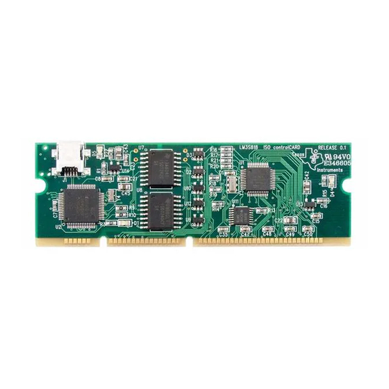
The Stellaris® LM3S818 controlCARD module is a DIMM form-factor module that can be used standalone or with a range of baseboards to accelerate evaluation and development. Texas Instruments offers a range of controlCARD baseboards for motor and power-control application. In most cases. these are available as complete kits that include a controlCARD module and a baseboard. -
Page 7: Compatibility Matrix
To start using the controlCARD module as a standalone module, see the MDL-LM3S818CNCD Read Me First document. To start using the controlCARD module in conjunction with a Texas Instruments’ controlCARD baseboard, see the Read Me First do November 17, 2011... -
Page 8: Chapter 2: Hardware Description
Hardware Description In addition to an LM3S818 microcontroller, the controlCARD module includes some simple multiplexing logic and an integrated Stellairs in-circuit debug interface (ICDI). This chapter describes how the hardware interfaces to the microcontroller. Figure 2-1 shows the controlCARD module block diagram. Figure 2-1. -
Page 9: Functional Description
Microcontroller and Interfaces (Schematic Page 2) LM3S818 Microcontroller The Stellaris LM3S818 is an ARM Cortex-M3-based microcontroller with 64-KB flash memory, 8- KB SRAM, 50-MHz operation, Motion control PWMs, and a wide range of other peripherals. Refer to the LM3S818 data sheet for complete device details. - Page 10 Hardware Description CCP2 31(DRV8301), CAP3 CAP3 36(DRV8312) CCP4 DAC_PWM1 DAC_PWM1 TRSTn TRSTn TRSTn U0Rx GPIO-28 (spare SCI Reset The RESET signal into the LM3S818 microcontroller connects to an R-C network (R1/C8) and to the ICDI circuit for a debugger-controlled reset. External reset is asserted (active low) under any one of these conditions: Power-on reset By the ICDI circuit when instructed by the debugger (this capability is optional, and may not be...
-
Page 11: Debug Interface, Virtual Com Port, And Isolators (Schematic
Stellaris® LM3S818 controlCARD Module User’s Manual Power Supplies The controlCARD module is typically powered by the baseboards via the DIMM edge connector. When used as a standalone module, without a baseboard, install wire jumpers to support USB-powered operation. WARNING – Do not install the wire power links if the controlCARD module is installed in a baseboard. -
Page 12: Figure 2-2. Controlcard Module Isolation
Hardware Description Figure 2-2. controlCARD Module Isolation The controlCARD module may be used without a baseboard. In order to power the non-isolated circuitry, power must be bridged across the isolation barrier as shown in Figure 2-3. November 17, 2011... -
Page 13: Chapter 3: Software Development
Generic Gnu C compiler Texas Instruments' Code Composer Studio™ IDE Baseboards from Texas Instruments may not support all toolchain options. Evaluation versions of these tools may be downloaded from www.ti.com/stellaris. Due to code size restrictions, the evaluation tools may not build all example programs. A full license is necessary to re-build or debug all examples. -
Page 14: Programming The Mdl-Lm3S818Cncd Controlcard Module
Software Development Programming the MDL-LM3S818CNCD controlCARD Module The MDL-LM3S818CNCD software package includes pre-built binaries for each of the example applications. If you installed StellarisWare to the default installation path (C:\StellarisWare), you can find the example applications in "C:\StellarisWare\boards\mdl-lm3s818cncd". The on-board Stellaris ICDI is used along with the Stellaris LM Flash Programmer tool to program applications on the MDL-LM3S818CNCD board. -
Page 15: Appendix A: Schematics
A P P E N D I X A Schematics This section contains the schematics for the LM3S818 controlCARD module: Stellaris Contents on page 16 Stellaris MCU on page 17 Stellaris ICDI on page 18 November 17, 2011... - Page 16 Page 2 - Stellaris - Edge Connector Page 3 - USB Debugger - Isolation TI Stellaris MCU 108 Wild Basin Rd. Suite 350 Austin, TX 78746 Designer: Drawing Title: Stellaris LM3S818 ControlCard Drawn by: Page Title: Title Page Approved: Size Document Number: MDL-LM3S818CNCD...
- Page 17 CAP1 CAP1/SDI CCP1 CAP2 CAP2/SDO CCP2 CAP3 CAP3/SCLK TI Stellaris MCU 108 Wild Basin Rd. Suite 350 Austin, TX 78746 Designer: Drawing Title: Stellaris LM3S818 ControlCard Drawn by: Page Title: Stellaris MCU Approved: Size Document Number: MDL-LM3S818CNCD 10/27/2011 Date: Sheet...
- Page 18 -.9 -.36 -354.9 6 608.52T.32 -.48 -1.74 0 -1.2 c -1.21.37 51.252 m f 6 -.9 -.36 -1-4735418 -1151.32 -.48 -1.74 0 -1.74 cB91.1.37 5.9252 m f 6 10/27/20 -.9 -.36 -2179478 354.4ET.32 -.48 -1.74 0 -1.2 c -1.29.37 51.252 8f 6 -.9 -.36 -42 1 860672( 1 ) 1 .32 -.48 -1.74 0 -1.74420 -1.749.37 5.9252 8f 6...
-
Page 19: Appendix B: Component Locations
Component Locations Figure B-1 shows the plot of the top-side component location and Figure B-2 shows the plot of the bottom-side component location. Figure B-1. Top-Side Component Location Figure B-2. Bottom-Side Component Location November 17, 2011... -
Page 20: Appendix C: References
Three-Phase PWM Motor Driver (DRV8312) Data Sheet, publication SLES256 Sensorless Trapezoidal Control of BLDC Motors Using BEMF Integration (InstaSPIN™ BLDC) on Stellaris® Microcontrollers Application Note, publication AN01289 Information on development tool being used: Texas Instruments’ Code Composer Studio™ IDE web site, www.ti.com/ccs November 17, 2011... - Page 21 Any exceptions to this are strictly prohibited and unauthorized by Texas Instruments unless user has obtained appropriate experimental/development licenses from local regulatory authorities, which is responsibility of user including its acceptable authorization.
- Page 22 FCC Interference Statement for Class B EVM devices This equipment has been tested and found to comply with the limits for a Class B digital device, pursuant to part 15 of the FCC Rules. These limits are designed to provide reasonable protection against harmful interference in a residential installation. This equipment generates, uses and can radiate radio frequency energy and, if not installed and used in accordance with the instructions, may cause harmful interference to radio communications.
- Page 23 Also, please do not transfer this product, unless you give the same notice above to the transferee. Please note that if you could not follow the instructions above, you will be subject to penalties of Radio Law of Japan. Texas Instruments Japan Limited (address) 24-1, Nishi-Shinjuku 6 chome, Shinjuku-ku, Tokyo, Japan...
- Page 24 EVALUATION BOARD/KIT/MODULE (EVM) WARNINGS, RESTRICTIONS AND DISCLAIMERS For Feasibility Evaluation Only, in Laboratory/Development Environments. Unless otherwise indicated, this EVM is not a finished...
- Page 25 IMPORTANT NOTICE Texas Instruments Incorporated and its subsidiaries (TI) reserve the right to make corrections, enhancements, improvements and other changes to its semiconductor products and services per JESD46, latest issue, and to discontinue any product or service per JESD48, latest issue.