Table of Contents
Advertisement
Quick Links
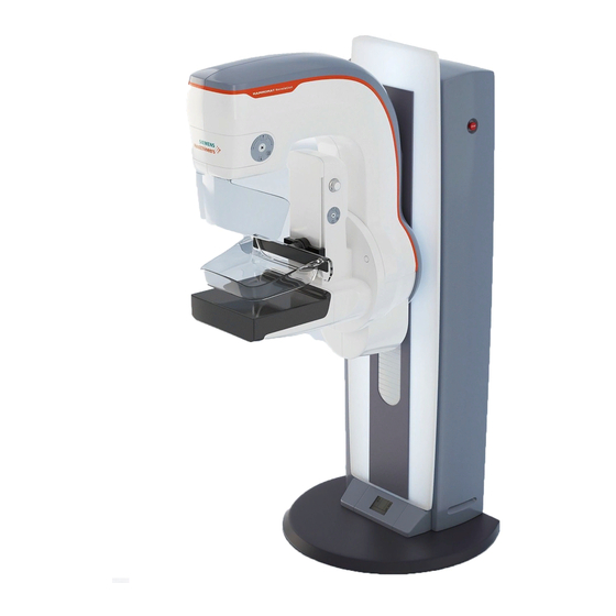
MAMMOMAT Balance
Maintenance Instructions
The Maintenance Protocol
SPB7-115.832.01...
is required for this instruction
Print No.: SPB7-115.831.01.01.02
Replaces: n.a.
X
SP
© Siemens AG 2004
The reproduction, transmission or
use of this document or its contents
is not permitted without express
written authority. Offenders will be
liable
for
damages.
All
including rights created by patent
grant or registration of a utility model
or_
design,
_are_
reserved.
English
Doc. Gen. Date: 05.04
rights,
Advertisement
Table of Contents

Related Manuals for Siemens MAMMOMAT


Summary of Contents for Siemens MAMMOMAT
- Page 1 MAMMOMAT Balance Maintenance Instructions © Siemens AG 2004 The reproduction, transmission or The Maintenance Protocol use of this document or its contents is not permitted without express SPB7-115.832.01… written authority. Offenders will be liable damages. rights, is required for this instruction...
- Page 2 Assemblers and other persons who are not employed by or otherwise directly affiliated with or autho- rized by Siemens or one of its affiliates are directed to contact one of the local offices of Siemens or one of its affiliates before attempting installation or service procedures.
-
Page 3: Table Of Contents
4 COMPRESSION SYSTEM........................11 5 ROTATING ANODE STA RTER......................12 6 FILAMENT .............................14 7 HIGH TENSION POWER SUPPLY......................15 8 MISCELLANEOUS..........................18 9 FINAL TESTS............................21 10 CHANGES TO PREVIOUS VERSION ....................22 MAMMOMAT Balance SPB7-115.831.01 Page 3 of 22 Siemens AG Maintenance Instructions Rev.01 05.04... - Page 4 Contents This page intentionally left blank. MAMMOMAT Balance SPB7-115.831.01 Page 4 of 22 Siemens AG Maintenance Instructions Rev.01 05.04 Medical Solutions...
-
Page 5: General Information
Service PC with serial port (connection cable is supplied with the unit) • MAMMOMAT Balance SSW (Service Software Program is supplied with the unit) • SIB phantom or Normi 7 or 4 cm Plexi or customer phantom (supplied by customer) •... -
Page 6: Text Emphasis
NOTE contains information provided with special emphasis to facilitate proper NOTE use of the equipment or proper execution of a procedure, i.e. hints, tips. MAMMOMAT Balance SPB7-115.831.01 Page 6 of 22 Siemens AG Maintenance Instructions Rev.01... -
Page 7: Safety Information And Preventive Measures
Tests or adjustments that must be made with radiation switched on are identified with the radiation warning symbol . During these types of adjustments, radiation protective clothing must be worn. MAMMOMAT Balance SPB7-115.831.01 Page 7 of 22 Siemens AG Maintenance Instructions Rev.01... -
Page 8: Explanation Of Abbreviations
CS No. Customer- Specific Number Installed Volume Components 1.8 Symbols Checks and adjustments that must be performed with radiation ON are identified by the radiation warning symbol. MAMMOMAT Balance SPB7-115.831.01 Page 8 of 22 Siemens AG Maintenance Instructions Rev.01 05.04... -
Page 9: System
Is the rotation smooth and noiseless through the entire range? • Is the rotation brake holding the C-Arm position? • Is the mechanical goniometer functional? • Is the C-Arm rotation disabled without table? MAMMOMAT Balance SPB7-115.831.01 Page 9 of 22 Siemens AG Maintenance Instructions Rev.01 05.04... -
Page 10: Column Stand
Manually activate safety switches MW2 (up) and MW1 (down) when carriage is at safety distance. Lifting carriage must be blocked. Vertical travel • Is the vertical travel smooth and noiseless? MAMMOMAT Balance SPB7-115.831.01 Page 10 of 22 Siemens AG Maintenance Instructions Rev.01... -
Page 11: Compression System
If thickness value is not correct refer to service instructions SPB7-115.840.01…, chapter of dosimeter where source to skin distance calibration is described. Breast thickness is obtained by such value subtracted by F.F.D. MAMMOMAT Balance SPB7-115.831.01 Page 11 of 22 Siemens AG Maintenance Instructions Rev.01... -
Page 12: Rotating Anode Starter
LED2 (yellow) bright during breaking or alarm LED3 (yellow) bright during breaking LED5 (green) bright in stand by or rotation LED6 (green) bright during rotation MAMMOMAT Balance SPB7-115.831.01 Page 12 of 22 Siemens AG Maintenance Instructions Rev.01 05.04 Medical Solutions... - Page 13 If upon log file inspection high duty comes in evidence it’ recommended to disable anode rotation brake to reduce operative tube assembly temperature. For more details refer to service instructions SPB7-115.840.01…. MAMMOMAT Balance SPB7-115.831.01 Page 13 of 22 Siemens AG Maintenance Instructions Rev.01...
-
Page 14: Filament
LED3 Bright if small focus is selected LED4 Bright if Filament is ON LED5 Bright during x-ray exposure. Brightness is proportional to tube anode current. More details can be found in Service Instruction SPB7-115.840.01…. MAMMOMAT Balance SPB7-115.831.01 Page 14 of 22 Siemens AG Maintenance Instructions Rev.01... -
Page 15: High Tension Power Supply
DVM 1000Vdc f.s. or oscilloscope with 1:100 1000Vdc probe can be connected to TP1/TP2 (GND) of PCB 94-132, see page 17. • Remove any table, select Manual Mode and an mAs value high enough to allow stable reading. MAMMOMAT Balance SPB7-115.831.01 Page 15 of 22 Siemens AG Maintenance Instructions Rev.01... - Page 16 A tube that shows metallization problems on the ray window does not allow correct non invasive measurement of the kV and MUST nevertheless be replaced. The most reliable and precise measurement is done with an external HV divider. MAMMOMAT Balance SPB7-115.831.01 Page 16 of 22...
- Page 17 PMF CONTROL LED Green LED1 indicates that fuse F2 of PCB 94-132 is OK. Yellow LED 2 turns on during exposure and can be used to verify continuous or pulsated X-ray emission. MAMMOMAT Balance SPB7-115.831.01 Page 17 of 22 Siemens AG Maintenance Instructions Rev.01...
-
Page 18: Miscellaneous
Install Grid table 18x24 • Install 18x24 collimation plate • Select LARGE focus • Remove compression plate • Remove cassette • Select ZERO POINTS technique MAMMOMAT Balance SPB7-115.831.01 Page 18 of 22 Siemens AG Maintenance Instructions Rev.01 05.04 Medical Solutions... - Page 19 Position the SIB phantom over 2 cm Plexiglas or other IQ phantom (e.g.Normi 7). • Select Zero Point mode and automatic decompression. • Compress somewhat and release an exposure. MAMMOMAT Balance SPB7-115.831.01 Page 19 of 22 Siemens AG Maintenance Instructions Rev.01...
- Page 20 8 Miscellaneous Phantom exposures • Compare the phantom exposures with those on hand and / or archive them for the next maintenance as starting values. MAMMOMAT Balance SPB7-115.831.01 Page 20 of 22 Siemens AG Maintenance Instructions Rev.01 05.04 Medical Solutions...
-
Page 21: Final Tests
Clean the unit using the materials recommended in the Instructions for use and repair any damaged paint. • System ON. QSQ Final test exposure • Take one final test exposure. MAMMOMAT Balance SPB7-115.831.01 Page 21 of 22 Siemens AG Maintenance Instructions Rev.01 05.04... -
Page 22: Changes To Previous Version
10 Changes to previous version 10 Changes to previous version Chapter Page Change n.a. n.a. n.a. MAMMOMAT Balance SPB7-115.831.01 Page 22 of 22 Siemens AG Maintenance Instructions Rev.01 05.04 Medical Solutions...