Table of Contents
Advertisement
Available languages
Available languages
Quick Links
www.wolf.eu
Montageanleitung Endmontage-Set
PushPull Lüftungssysteme
FWL-PushPull-30 (TwinUnit)
DE
FWL-PushPull-30 RC (TwinUnit)
FWL-PushPull RLS
FWL-PushPull RLS-K
Deutsch
Installation instructions for final installation kit
PushPull ventilation systems
FWL-PushPull-30 (TwinUnit)
GB
FWL-PushPull-30 RC (TwinUnit)
FWL-PushPull RLS
FWL-PushPull RLS-K
English
7100904 | 202202
Advertisement
Chapters
Table of Contents

Related Manuals for Wolf FWL-PushPull-30


Summary of Contents for Wolf FWL-PushPull-30
- Page 1 Montageanleitung Endmontage-Set PushPull Lüftungssysteme FWL-PushPull-30 (TwinUnit) FWL-PushPull-30 RC (TwinUnit) FWL-PushPull RLS FWL-PushPull RLS-K Deutsch Installation instructions for final installation kit PushPull ventilation systems FWL-PushPull-30 (TwinUnit) FWL-PushPull-30 RC (TwinUnit) FWL-PushPull RLS FWL-PushPull RLS-K English 7100904 | 202202...
-
Page 2: Table Of Contents
8.2 Geräteaufbau und Positionierung... Anschlussplan FWL-PushPull-30 8.3 Verlängerungsrohr kürzen ....RC – Geräteanschluss ....8.4 Dichtungsbänder aufkleben.... Produktdatenblätter ......62 8.5 Geräteeinschub FWL-PushPull-30 / FWL-PushPull-30 ......62 FWL-PushPull-30 RC mit Verlän- gerungsrohr einbauen ....8.6 Elektrischer Anschluss 230 V ..8.7 Raumluftsteuerungen anschließen. -
Page 3: Steuerungskonzept Fwl-Pushpull-30
Steuerungskonzept FWL-PushPull-30 (TwinUnit) FWL-PushPull-30 (TwinUnit) Steuerungskonzept FWL-Push- Pull-30 (TwinUnit) 7100904 | 202202 WOLF GmbH | 3... -
Page 4: Steuerungskonzept Rc Mixed Systeme
Steuerungskonzept RC Mixed Systeme FWL-PushPull-30 (TwinUnit) Steuerungskonzept RC Mixed Systeme 4 | WOLF GmbH 7100904 | 202202... -
Page 5: Vorwort
Der Abluftbetrieb startet in Abhängigkeit der Einstellung vollautomatisch Für Zubehörkomponenten → Beiblatt der Zube- oder auch manuell per Tastendruck. hörkomponente. FWL-PushPull-30 (TwinUnit) sind als Einzelge- räte oder im Verbund mit weiteren FWL-Push- Pull-30 (TwinUnit)/FWL-PushPull-45-Geräten einsetzbar. FWL-PushPull-30 (TwinUnit) verfü- 7100904 | 202202... -
Page 6: Anwendungsbeispiel
Ventilatoren die Feuchtigkeit hinaus beför- dern (keine Wärmerückgewinnung). Nicht möglich / nicht zulässig ist: In Kombination mit Einzelraum-Lüftungsgeräten ● ein Betrieb von FWL-PushPull-30 (TwinUnit)- FWL-PushPull-45 für Zulufträume lässt sich dar- Geräten in Verbindung mit einer FWL-PushPull über hinaus ein dezentrales Lüftungssystem für RLS-Steuerung. -
Page 7: Technische Daten
6 Technische Daten FWL-PushPull-30 (TwinUnit) FWL-PushPull-30 (TwinUnit)-Gerät mit Leistungsaufnahme 1,7 / 2,5 / 3,4 / 4,4 / balanciertem Betrieb für die Dauerlüftung 5,3 W im Bad Wärmebereitstel- 73,3 % (Stufe 3) Raumluftsteuerung FWL-PushPull RLS-K lungsgrad Zuluft- und Abluft mit Richtungswechsel 0,19 W / (m³/h) SEC-Wert A (-39,71 kWh / (m²*a)) -
Page 8: Geräteübersicht Und Anschlussmög- Lichkeiten
Pull RLS-K Zusatzfunktionen K1-K5: Zuluftfunktion für FWL-ABLV-Abluftbe- trieb K6-K8: Volumenstromausgleich ABL-Betrieb über Außenluftdurchlass K9-K12: Zuluftfunktion für FWL-PushPull-30 (TwinUnit)-Abluftbetrieb. Hinweis: Volumenstromausgleich nur für 1 FWL- PushPull-30 (TwinUnit)-Gerät möglich. * Bei der Verwendung von FWL-PushPull RLS- LTRC können max. 8 Funksensoren und max. -
Page 9: Kombinationen K13-K18 (Fwl-Pushpull Rls)
230 V-Eingang EnOcean- RLS-RC RLS-K + Funk FWL-PushPull RLS-LTRC beliebig Zusatzfunktionen K19: Anzahl beliebig sofern in Reichweite. Zuluft- zuführung nur von 2x FWL-PushPull-45 RC Ge- räten. * Nur kabelgebundene Abluftgeräte zulässig (kei- ne RC-Abluftgeräte verwenden). 7100904 | 202202 WOLF GmbH | 9... -
Page 10: Montage
• Bei Überschreitung der maximal angegebenen Kabellängen können Disbalancen entstehen. • Ein manuell geschalteter Abluftbetrieb oder In- Installationsvorgaben bzgl. der Kabellängen tensivlüftung ist am FWL-PushPull-30 RC und -typen beachten. (TwinUnit) mittels FWL-PushPull RLS-RC oder bauseitigem Taster möglich. Die Dauer • Lüftungsgeräte nur mit der auf dem Typenschild der manuell geschalteten Funktion ist über den... -
Page 11: Geräteaufbau Und Positionierung
Gehäuseteilen, z. B. rohren müssen verlegt sein. am Schnittgrat. Zum Kürzen des Verlängerungsrohrs wie folgt Schutzhandschuhe benutzen. vorgehen: 9. Verlängerungsrohr absägen x + 5 mm. Säge- schnitt entgraten. 4 Zentrierungsring 5 Verlängerungsrohr 6 Zentrierungsring 7100904 | 202202 WOLF GmbH | 11... -
Page 12: Dichtungsbänder Aufkleben
Dichtungsbänder korrekt einkleben. Schalters wird der zweite Eingang mit zugehö- 8.5 Geräteeinschub FWL-Push- riger Tülle verwendet → Abbildung. Pull-30 / FWL-PushPull-30 RC mit Verlängerungsrohr einbauen 6. Komplette Einschubeinheit mit Innenabde- ckung ein wenig in die Wandhülse einschie- ben. Anschlussleitung(en) durch die Leitungs- tülle(n) in den Anschlussraum führen. -
Page 13: Elektrischer Anschluss
6 Ventilatoren (bis 3 FWL-PushPull-30 (TwinUnit)) bereitgestellt. FWL-PushPull-30 (TwinUnit)-Geräte • Die Raumluftsteuerung wird mit 230 V AC ver- sorgt. • Die Gerätevariante FWL-PushPull-30 RC (TwinUnit) verfügt über eine vollständig inte- 12.Elektronikfachabdeckung aufsetzen und ver- grierte Steuereinheit mit 230 V-Anschluss. schrauben (2 Schrauben). -
Page 14: Raumluftsteuerungen Anschließen
8.7.1 Kabelgebundene Systeme Eine Master-Raumluftsteuerung FWL-PushPull RLS oder FWL-PushPull RLS-K kann mit maxi- mal 3 weiteren Leistungsteilen und/oder bauglei- chen Slave-Raumluftsteuerungen erweitert wer- den. In einem FWL-PushPull-45-Lüftungssystem lassen sich also maximal 4 Steuereinheiten ein- setzen. 14 | WOLF GmbH 7100904 | 202202... -
Page 15: Fwl-Pushpull Rls-K Anschließen
FWL-Push- Pull-45 RC Pull-30 RC Pull-45 (TwinUnit) FWL-Push- Pull-30 RC (TwinUnit) Raumluftsteuerung FWL-PushPull RLS-K wird für die Ansteuerung von FWL-PushPull-30 … oder (TwinUnit)-Geräten eingesetzt. max. 3 1. Rahmen der Raumluftsteuerung abnehmen. / FWL-Push- 2. FWL-PushPull-30 (TwinUnit)-Geräte am RS Pull-30 485 Bus anschließen. -
Page 16: Einbau Feuchtesensor Flw-Push-Pull Rh Sensor Int. In Flw-Push-Pull Rls / Rls-K
Service-Mode an und stellen Sie den gewünschten Parameterwert ein. Zusatz- informationen erhalten Sie in der Inbetrieb- nahmeanleitung im Internet (Download unter www.WOLF.eu). Hier können Sie auch die In- betriebnahmesoftware für die FWL-PushPull RLS-K-Steuerung downloaden. Mit dieser steht Ihnen eine Vielzahl an Einstellparame- tern für individuelle Systemanpassungen zur... -
Page 17: Service-Mode - Bedienung
Parameterwert ändern Mode automa- Hat man ein Nach der Än- tisch beendet. bestimmtes derung des Untermenü Parameters erreicht, kön- blinken die nen mit die- Lüftungsstu- sen Tasten fen-LEDs. die Parame- ter eingestellt werden. 7100904 | 202202 WOLF GmbH | 17... -
Page 18: Service-Menü Fwl-Pushpull Rls
(Fan1/Fan2) Hier wird die Typenfamilie ausge- wählt, die an der Lüfterschnittstelle Fan1/Fan2 angeschlossen wird. Achtung: Es sind nur sortenreine Gerätekombinationen FWL-Push- Pull-45 oder FWL-PushPull-30 an der Lüfterschnittstelle zulässig! Anzahl Gerätepaare / Geräte 1 Gerätepaar FWL-PushPull-45 an FWL-PushPull (Fan1/ oder 1 FWL-PushPull-30 Fan2) 2 Gerätepaare FWL-PushPull-45... - Page 19 Zur Verfügung stehen der interne Sen- sor FWL-PushPull RH Sensor int. und die externen Sensoren FWL- PushPull RH Sensor ext., FWL- PushPull CO2 Sensor ext. und Pu- shPull VOC Sensor ext. 7100904 | 202202 WOLF GmbH | 19...
- Page 20 Modbus-Schnittstelle ist der Anschluss von externen Senso- ren/LTs/RLS nicht möglich. ModBus-Adresse Adresse 10 Adresse 11 Adresse 12 Adresse 13 Adresse 14 Adresse 15 Adresse 16 Mit diesem Einsteller wird die ModBus Adresse gewählt. 20 | WOLF GmbH 7100904 | 202202...
-
Page 21: Service-Menü Fwl-Pushpull Rls-K
FWL-PushPull-45 (Fan1/Fan2) Hier wird die Typenfamilie ausge- wählt, die an der Lüfterschnittstelle Fan1/Fan2 angeschlossen wird. Achtung: Es sind nur sortenreine Gerätekombinationen FWL-Push- Pull-45 oder FWL-PushPull-30 an der Lüfterschnittstelle zulässig! Anzahl Gerätepaare/Geräte an 1 Gerätepaar FWL-PushPull-45 FWL-PushPull (Fan1/Fan2) oder 1 FWL-PushPull-30 2 Gerätepaare FWL-PushPull-45 oder 2 FWL-PushPull-30... - Page 22 RLS-Kombinationen zulässig! 230 VAC-Eingang Einschlafmodus Stoßlüftung Sicherheitsabschaltung Zuluftbetrieb ohne Nachlauf Zuluftbetrieb mit Nachlaufzeit 6 Min. Zuluftbetrieb mit Nachlaufzeit 15 Min. Zur Einstellung einer Zusatzfunkti- on. Diese kann mit einem Taster oder Schalter am 230 V-Eingang aktiviert werden. 22 | WOLF GmbH 7100904 | 202202...
- Page 23 PushPull RH Sensor ext., FWL- PushPull CO2 Sensor ext. und Pu- shPull VOC Sensor ext. EnOcean EnOcean-Modul nicht vorhan- EnOcean-Modul vorhanden Mit diesem Einsteller wird der Ein- satz des EnOcean-Erweiterungs- moduls (FWL-PushPull RLS- LTRC) freigeschaltet. 7100904 | 202202 WOLF GmbH | 23...
- Page 24 Schnittstelle ist der Anschluss von FWL-PushPull-30 (TwinUnit) oder von externen Sensoren/LTs/ RLS nicht möglich. ModBus-Adresse Adresse 10 Adresse 11 Adresse 12 Adresse 13 Adresse 14 Adresse 15 Adresse 16 Mit diesem Einsteller wird die ModBus Adresse gewählt. 24 | WOLF GmbH 7100904 | 202202...
-
Page 25: Service-Menü Fwl-Pushpull Rls-Rc
Manuell (rote LED 2x) Intensivlüftung Automatik / Abluftbetrieb Manuell (rote LED 3x) Intensivlüftung Automatik / Intensivlüftung Manuell (rote LED 4x) Hier kann die Entfeuchtungsfunktion für den Sensor (Auto) und für den Taster (manuell) eingestellt werden. 7100904 | 202202 WOLF GmbH | 25... - Page 26 Die blaue Be- Einzelraumlüf- Paarweiser Betrieb (rote LED 1x) triebsarten- tungsgerät Einzelraumlüftungsgerät (rote LED 2x) LED blinkt zy- Bei Empfangsproblemen zum Slave bzw. klisch je 4x Mastergerät kann das FWL-PushPull-30 RC (TwinUnit)-Gerät als Einzelraumlüftungsgerät freigeschaltet werden. 26 | WOLF GmbH 7100904 | 202202...
-
Page 27: Ersatzteile
örtlichen Vorschriften. Ventilatoranschluss- 2578032 platine FWL-Push- Pull-30 (TwinUnit) Impressum Funkplatine FWL- 2578033 © Wolf GmbH. Deutsche Original-Betriebsanlei- PushPull-30 RC tung. Druckfehler, Irrtümer und technische Ände- (TwinUnit) rungen vorbehalten. Die in diesem Dokument er- Abdeckung Elektro- 2578028 wähnten Marken, Handelsmarken und geschützte nik Funkplatine Warenzeichen beziehen sich auf deren Eigentü-... - Page 28 8.3 Shortening extension duct ....Product data sheets ......62 8.4 Gluing on sealing bands ....FWL-PushPull-30 ......62 8.5 Installing FWL-PushPull-30 / FWL- PushPull-30 RC slide-in module with extension duct ......8.6 230 V electrical connection..... 8.7 Connecting room air controls..
-
Page 29: Fwl-Pushpull-30 Control Concept (Twinunit)
FWL-PushPull-30 control concept (TwinUnit) FWL-PushPull-30 (TwinUnit) FWL-PushPull-30 control concept (TwinUnit) 7100904 | 202202 WOLF GmbH | 29... -
Page 30: Rc Mixed Systems Control Concept
RC Mixed Systems control concept FWL-PushPull-30 (TwinUnit) RC Mixed Systems control concept 30 | WOLF GmbH 7100904 | 202202... -
Page 31: Fwl-Pushpull-30 Rc
For information on filter changes, set- 1946-6. ting the operating modes and ventila- FWL-PushPull-30 (TwinUnit) are balanced vent- tion levels → Brief instructions on fil- ilation units, which are the ideal choice for use in ter changes, operating modes, ventil- exhaust air rooms (bathroom, WC or kitchen ation levels. -
Page 32: Application Example
Ventilation solution for a 3-room flat with determined depending on the unit variant used. FWL-PushPull-30 (TwinUnit) ventilation units FWL-PushPull-30 (TwinUnit) are installed in ex- for the bathroom and FWL-PushPull-45 ventila- terior walls (wall thickness 320-790 mm, installa- tion units for living spaces... -
Page 33: Technical Data
6 Technical data FWL-PushPull-30 (TwinUnit) FWL-PushPull-30 (TwinUnit) unit with Volumetric flow in 5 / 12 / 18 / 22 / 26 m³/h balanced operation for continuous ventila- heat recovery mode, tion in the bathroom ventilation levels 1 to Room air control FWL-PushPull RLS-K Volumetric flow in ex- 45 m³/h... -
Page 34: Unit Overview And Connection Options
K9-K12: Supply air function for FWL-Push- Pull-30 (TwinUnit) exhaust air mode. Note: Volumetric flow compensation only pos- sible for 1 FWL-PushPull-30 (TwinUnit) unit. * If using FWL-PushPull RLS-LTRC a max. of 8 radio sensors and a max. of 4 FWL-PushPull-45 RC (master) can be taught-in. -
Page 35: Combinations K13-K18 (Fwl-Pushpull Rls)
FWL-PushPull RLS-LTRC Additional functions K19: Any number provided they are within range. Supply air only from 2 FWL-PushPull-45 RC units. *Only wired exhaust air units are permitted (do not use RC exhaust air units). 7100904 | 202202 WOLF GmbH | 35... -
Page 36: Installation
• For prescribed connection lines → Connection ally switched intensive ventilation is possible on and wiring diagrams [} 54]: FWL-PushPull-30 (TwinUnit) units with a but- • Grid connection and 230 V input: Type NYM-J ton or switch (provided by the customer). When 5G1, 5 mm²... -
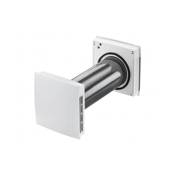
Page 37: Unit Structure And Positioning
8.4 Gluing on sealing bands To shorten the extension duct, proceed as fol- lows: 3 Fluid separator, outside 3.1 Sealing strip 5 Extension duct 4 Centring ring 7 Sealing strip 5 Extension duct 6 Centring ring 7100904 | 202202 WOLF GmbH | 37... -
Page 38: Installing Fwl-Pushpull-30 / Fwl-Pushpull-30 Rc Slide-In Module With Extension Duct
8 Installation FWL-PushPull-30 (TwinUnit) 1. Glue sealing strips onto the outside of the duct 5. If using FWL-PushPull-30 (TwinUnit) units end of the fluid separator and/or onto the out- and connection of an optional button or switch, side of the extension duct so that it terminates the second input is used with the relevant flush at the face end. -
Page 39: Electrical Connection
(up to 3 FWL-PushPull-30 (TwinUnit)). • The room air control is supplied with 230 V AC. FWL-PushPull-30 (TwinUnit) units #3 • The unit variant FWL-PushPull-30 RC (Twin- Unit) has a fully integrated control unit with 230 V connection. Note the following safety instructions. -
Page 40: Connecting Room Air Controls
FWL-PushPull RLS / FWL-PushPull RLS-K grams [} 54]. generally takes place on the terminal block of • If a FWL-PushPull-30 (TwinUnit) unit is run- Fan1 or Fan2. ning in exhaust air mode, the FWL-Push- Pull-45 units handle the volumetric flow com- 8.7.2 Radio-controlled systems... -
Page 41: Installing Radio Switch (Enocean)
Extension module FWL-PushPull RLS-LTRC For installation and wiring of an external sensor→ can only be combined with FWL-PushPull-45 FWL-PushPull-45 / FWL-PushPull-30 (Twin- RC unit pairs. Wired operation is needed for Unit) installation and commissioning instructions. other unit types. -
Page 42: Commissioning
(down- ton for 2 accepted.*/** load at www.WOLF.eu). Here you can also seconds. download the commissioning software for the FWL-PushPull RLS-K control. This provides you with a wide range of setting parameters for individual system adjustments. -
Page 43: Fwl-Pushpull Rls Service Menu
(Fan1/Fan2) The type family, which is connec- ted to the Fan1/Fan2 interface, is selected here. Notice: Only single-type FWL- PushPull-45 or FWL-PushPull-30 unit combinations are permitted at the fan interface! Number of device pairs/ 1 FWL-PushPull-45 unit pair or devices on FWL-PushPull 1 FWL-PushPull-30... - Page 44 Select how many internal and ex- ternal sensors are connected/com- bined. The internal sensor FWL- PushPull RH Sensor int. and the external sensors FWL-PushPull RH Sensor ext., FWL-PushPull CO2 Sensor ext. and PushPull VOC Sensor ext. are available. 44 | WOLF GmbH 7100904 | 202202...
- Page 45 When the Modbus interface is active, external sensors/LTs/ RLS cannot be connected. ModBus address Address 10 Address 11 Address 12 Address 13 Address 14 Address 15 Address 16 This adjuster selects the ModBus address. 7100904 | 202202 WOLF GmbH | 45...
-
Page 46: Fwl-Pushpull Rls-K Service Menu
Odd number 5 FWL-PushPull-45 units The number of units connected to the fan interface (Fan1/Fan2) is selected here. Notice: Release/ number of FWL-PushPull-30 units is taken into account in another sub-menu (FWL-PushPull-30 parameters) Ventilation levels Ventilation level “0” possible Ventilation level “0” blocked If ventilation level “0”... - Page 47 Supply air mode with overrun time of 6 min. Supply air mode with overrun time of 15 min. For setting an additional function. This can be activated with a button or switch at the 230 V input. 7100904 | 202202 WOLF GmbH | 47...
- Page 48 RH Sensor ext., FWL-PushPull CO2 Sensor ext. and PushPull VOC Sensor ext. are available. EnOcean EnOcean module not present EnOcean module present This adjuster enables the use of the EnOcean expansion module (FWL-PushPull RLS-LTRC). 48 | WOLF GmbH 7100904 | 202202...
- Page 49 9600 Baud ModBus active 19200 Baud This adjuster activates the Mod- Bus and sets the baud rate. Notice: When the Modbus inter- face is active, FWL-PushPull-30 (TwinUnit) or external sensors/ LTs/RLS cannot be connected. ModBus address Address 10 Address 11...
-
Page 50: Fwl-Pushpull Rls-Rc Service Menu
Automatic intensive ventilation / Manual ex- haust mode (red LED 3x) Automatic intensive ventilation / Manual in- tensive ventilation (red LED 4x) The dehumidification function for the sensor (Auto) and for the button (Manual) can be set here. 50 | WOLF GmbH 7100904 | 202202... - Page 51 (red LED 2x) LED flashes If there are reception problems with the slave 4x per cycle or master device, the FWL-PushPull-30 RC (TwinUnit) unit can be enabled as a single- room ventilation unit. 7100904 | 202202 WOLF GmbH | 51...
-
Page 52: Spare Parts
(TwinUnit) fan con- nection board Company information FWL-PushPull-30 2578033 © Wolf GmbH. Translation of the original operat- RC (TwinUnit) ra- ing instructions. Misprints, errors and technical dio board changes are reserved. The brands, brand names Electronics cover for... -
Page 53: Einbaumaße, Bohrabstände
Einbaumaße, Bohrabstände / Installation dimensions, drilling distances FWL-PushPull-30 (TwinUnit) Einbaumaße, Bohrabstände / Installation dimensions, drilling distances Einbaumaße FWL-PushPull-30 / FWL-Push- Pull-30 RC / Installation dimensions for FWL-PushPull-30 / FWL-PushPull-30 RC Abmessungen weiterer Komponenten / Dimensions of further components Komponente Abmessungen... -
Page 54: Anschluss- Und Verdrahtungspläne
Anschluss- und Verdrahtungspläne / Connection and wiring diagrams FWL-PushPull-30 (TwinUnit) Anschluss- und Verdrahtungspläne / Connection and wiring diagrams Anschlussplan FWL-PushPull RLS-K – FWL- PushPull-30 / Connection diagram for FWL-PushPull RLS-K – FWL-PushPull-30 54 | WOLF GmbH 7100904 | 202202... -
Page 55: K - Fwl-Pushpull-30
Die Spannungsversorgung der FWL-Push- unit = 25 m. Pull-30 (TwinUnit) (+) MUSS am Anschluss Fan1 oder Fan2 erfolgen. Für Adressierung → The power supply to the FWL-PushPull-30 Geräteanschluss. (TwinUnit) (+) MUST come from the Fan1 or Fan2 connection. For addressing → Unit connection. -
Page 56: Anschlussplan Fwl-Pushpull Rls- K - Systembus
Anschluss- und Verdrahtungspläne / Connection and wiring diagrams FWL-PushPull-30 (TwinUnit) Anschlussplan FWL-PushPull RLS-K – Sys- tembus / Connection diagram for FWL-Pu- shPull RLS-K – system bus 56 | WOLF GmbH 7100904 | 202202... - Page 57 / FWL-Pu- stelle RS-485 shPull RLS-K via separate po- W1.X Anschlussleitung Bus (RS-485). Empfohlene Steuerleitung J-Y (ST) Y 2x2x0,8 mm. Max. Lei- tungslänge bis zu den Senso- ren, RLS, LTs und EnOcean- Modul ca. 100 m. Alternativ 7100904 | 202202 WOLF GmbH | 57...
-
Page 58: Anschlussplan Fwl-Pushpull-30
RLS, LTs and EnOcean module ap- prox. 100 m. Alternatively, this connection can also be used as a ModBus RTU interface. Anschlussplan FWL-PushPull-30 – Geräte- anschluss / Connection diagram for FWL- PushPull-30 – unit connection Schalter/Taster ABL-Betrieb/In- tensivlüftung, Auswahl Funkti- FWL-Push- Lüftungsgerät FWL-Push-... - Page 59 Fan 2 connecting cable Connecting cable switch/push- Pull-30 button for activation of special (TwinUnit) functions (exhaust air mode, in- Fan2 tensive ventilation), recommen- ded control cable LiYY 2x0.5 mm². Max. cable length 25 m. 7100904 | 202202 WOLF GmbH | 59...
-
Page 60: Connection Diagram For Fwl-Push
Anschluss- und Verdrahtungspläne / Connection and wiring diagrams FWL-PushPull-30 (TwinUnit) Anschlussplan FWL-PushPull-30 RC – Gerä- teanschluss / Connection diagram for FWL-PushPull-30 RC – Unit connection Netzanschlussleitung FWL-Pu- shPull-30 RC (TwinUnit), emp- FWL-Push- Lüftungsgerät FWL-Push- fohlene Anschlussleitung NYM-J Pull-30 RC Pull-30 RC (TwinUnit) 3x1,5 mm²... - Page 61 Pull-30 RC (TwinUnit) Fan2 Exhaust air mode/intensive ven- tilation button (selection of func- tion/service mode) FWL-PushPull-30 RC (TwinU- nit) mains connecting cable, re- commended connecting cable NYM-J 3x1.5 mm² Connecting cable button for acti- vation of special functions (ex- haust air mode, intensive venti- lation), recommended control cable LiYY 2x0.5 mm².
-
Page 62: Produktdatenblätter
Produktdatenblätter / Product data sheets FWL-PushPull-30 (TwinUnit) Produktdatenblätter / Product data sheets FWL-PushPull-30 / FWL-PushPull-30 62 | WOLF GmbH 7100904 | 202202... - Page 63 Notizen...
- Page 64 WOLF GmbH | Postfach 1380 | D-84048 Mainburg Tel. +49.0.87 51 74- 0 | Fax +49.0.87 51 74- 16 00 | www.WOLF.eu Anregungen und Korrekturhinweise gerne an feedback@wolf.eu. 0185.1229.0100_02.22...