
Related Manuals for Hawking HNC230G

Summary of Contents for Hawking HNC230G
- Page 2 Step 1: Check Contents & Installation Requirements Step 2: Physical Description Step 3: Hardware Installation Step 4: Run the Quick Setup Wizard Step 5: Viewing & Tips...
- Page 3 Congratulations on the purchase of your new Hawking Net- Vision HNC230G Wireless-G Network Camera. HNC230G is a high performance standalone camera system that provides an ideal solution for remote monitoring, surveillance, or sending live video over the Internet. The camera offers a broad...
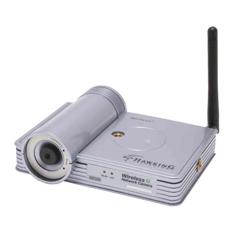
- Page 5 Front Panel LED: Link/Activity LED: Ready LED: Lens & Manual LED: Focus Ring WLAN LEDs - Link/Activity: Green when monitoring - Ready: Orange when device is powered on & ready for access - WLAN: lit for wireless link; flashing for video transmission/reception - LAN: lit for wired link;...
- Page 6 Back Panel Power Reset Input Button Antenna Port...
- Page 7 Locate the antenna connector on the left side of the camera’s rear panel. Screw the base of the antenna (included with the HNC230G) into antenna connector. Locate the network cable connector (RJ-45 port) on the camera’s rear panel. Connect an Ethernet cable to the port.
- Page 8 Locate the power input connector on the camera’s rear panel, and attach the external power supply. Then, plug the adapter into an available outlet. Please check to see that the orange “Ready” LED located next to the lens of the camera (front side) is lit to ensure that the camera is powered on.
- Page 9 Insert the Hawking Net-Vision HNC230G Installation & Utilities CD into your CD-ROM Drive. When the main page loads, click on Quick Setup Wizard.
- Page 10 The Setup Wizard will search for similar cameras available on your local area network. A “similar” camera will have the same code of four letters at the beginning of its serial number. This code is “HEMT” and can be found on either the right or left panel of the box, or on the label on the bottom of the camera.
- Page 11 Each available camera will be displayed in the camera list with its MAC address, current default IP address, and model number. (NOTE: The Setup Wizard may display an IP address for the camera that is already consistent with your network [LAN] settings, rather than the default one.) In the camera list, click on the camera you would like to configure so that it is highlighted blue, and then click Next.
- Page 12 Next, the login username and password screen will appear. Please type in the default login and password and then press “OK”. The default values are: Login: admin Password: 1234 If you have already set a username and password, enter them and press “OK”.
- Page 13 The Setup Wizard will try to determine your network settings. If a DHCP server is present on your network, the Wizard will obtain your network settings and automatically configure your network camera to operate on your LAN by returning network settings that are consistent with your network.
- Page 15 The Wireless Network setup screen will allow you to connect your wireless network camera to your wireless router, access point, or point-to-point ad-hoc connection.
- Page 16 Please highlight the appropriate wireless network that you would like to assign the network camera to. You may choose to scan for the following two types of networks: Infrastructure (If you are using a router or access point) or Ad-hoc (for peer- to-peer connection).
- Page 18 To protect your camera from unauthorized access and use, you will need to change the Admin Password, which is “1234” by default. The password can have a maximum of four characters. Confirm the new password by typing it again identically in the “Reconfirm” field. Click Next once you have confirmed your new password.
- Page 19 The following status page will appear. It will display a summary of the changes you have made to the network camera’s settings. If all the settings are correct, click Next to continue.
- Page 20 The setup process has now been completed. Please briefly review the text on the page before clicking on Reboot. After clicking Reboot, the Setup Wizard will close. Please allow about 45 seconds to one minute for the camera to reboot. After the camera has finished rebooting, you can type in its new IP address in your web browser to begin accessing the camera.
- Page 21 Example on How to Set the IP Address Manually The example shown here illustrates how to manually set an IP address using the Windows XP operating system. However, the procedure is similar for all other versions of Windows. When setting an IP address, you must make sure that the address you specify has the same first three octets (or segments) as the other devices on your LAN.
- Page 22 Click on Start in the bottom left corner of your screen. Then click on My Network Places.
- Page 23 Click on View Network Connections.
- Page 24 In the Network Connections window, you should see an icon titled Local Area Connection (or something similar). You can access this icon in two ways: a. by clicking or double- clicking on it, or b. by right-clicking on it and then clicking on Status from the resulting menu.
- Page 25 A window with the title Local Area Connection Status (or something similar) will appear. Click on the Support tab. Under the heading Address Type, you will find an IP Address line and a Default Gateway line. These two lines will have IP addresses with the first three octets in common. Use this information to set the IP address for your network camera.
- Page 27 • You can access and view your network camera’s images via a web browser by typing “http://IPAddressofCamera” in the address bar. • You can also use the included software application to view, record, and playback the network camera’s images. • The example illustrated in the previous section “Step 4: Run the IP Setup Program”...