Advertisement
Available languages
Available languages
Quick Links
Introduction
Use this instruction to replace the integrated LED light module. The images
throughout this manual are for reference only and your product may look
different.
You will need:
• 1/4" magnetic nut driver
• Long-nosed pliers
• 5/16" long-shafted magnetic nut driver and socket
• Flathead screwdriver
Instructions
1. Disconnect the electrical and battery power (if applicable) to the garage
door opener. Remove the battery and place in a safe location.
2. Remove the control door panel from both ends of
the opener. (A)
a. Separate the hinges in
opposite directions.
b. Remove the panels from
the hinge setting and
place in a safe location.
3. Disconnect the door control
wires from the RED and
WHITE terminals and the
safety reversal sensor wires
from the BLACK and WHITE
terminals. (B)
4. Remove the end panels from
both ends of the opener.
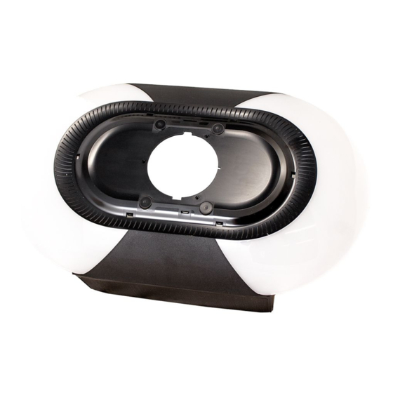
5. Remove the integrated LED
light module from the
opener. (C)
6. Disconnect the ORANGE and WHITE wire harness from plug to the
integrated LED light module and set aside cover / LED light module. (D)
7. Install the new integrated LED light module.
C
Control Door Panel
Integrated LED Light Module
A
B
End Panel
D
Integrated LED Light Module
Repair Parts 041-0200-000, 041-0201-000,
041-0202-000 and 041-0203-000
To prevent possible SERIOUS INJURY or DEATH:
• Disconnect ALL electric and battery power BEFORE performing ANY
service or maintenance.
To prevent damage to the receiver logic board, DO NOT touch printed
circuit board of replacement receiver/logic board during installation.
ALWAYS wear protective gloves and eye protection when changing the
battery or working around the battery compartment.
WARNING: This product can expose you to chemicals including
lead, which are known to the State of California to cause cancer or
birth defects or other reproductive harm. For more information go to
www.P65Warnings.ca.gov.
8. Connect the ORANGE and WHITE wire harness from the plug to the
Integrated LED Light Module. (D)
9. Align integrated LED light module to chassis screw holes.
10. Attach both end panels.
11. Reconnect the door control and safety reversal sensor wires. (B)
Door Control:
• WHITE wire into the WHITE terminal.
• WHITE/RED wire into the RED terminal.
Safety Reversal Sensors:
• WHITE wires into the WHITE terminal.
• WHITE/BLACK wires into the GRAY terminal.
12. Reattach the control door panels.
13. Reconnect power to the opener.
14. Test the Protector System.
Replacement
Advertisement

Related Manuals for Chamberlain 041-0200-000


Summary of Contents for Chamberlain 041-0200-000
- Page 1 Integrated LED Light Module Replacement Repair Parts 041-0200-000, 041-0201-000, Introduction 041-0202-000 and 041-0203-000 Use this instruction to replace the integrated LED light module. The images throughout this manual are for reference only and your product may look different. You will need: To prevent possible SERIOUS INJURY or DEATH:...
- Page 2 © 2021, Chamberlain All rights reserved Tous droits réservés 114-5536-000 Todos los derechos reservados...
- Page 3 Remplacement du module intégré ® ® d’éclairage à DEL Pièces détachées 041-0200-000, 041-0201-000, Introduction 041-0202-000 et 041-0203-000 Utilisez ces instructions pour remplacer le module intégré d’éclairage à DEL. Les images de ce manuel sont fournies à titre indicatif uniquement et il est possible que votre produit soit différent.
- Page 4 © 2021, Chamberlain All rights reserved Tous droits réservés 114-5536-000 Todos los derechos reservados...