Table of Contents
Advertisement
Quick Links
Advertisement
Table of Contents

Related Manuals for Chamberlain LiftMaster CB202EV


Summary of Contents for Chamberlain LiftMaster CB202EV
- Page 1 ® Instruction CB202EV...
-
Page 2: Table Of Contents
TOPIC PAGE SAFETY RULES ..................1 TYPICAL CONFIGURATION OF A UNIT . -
Page 3: Safety Rules
WARNING / ATTENTION IMPORTANT FITTING AND OPERATING INSTRUCTIONS PLEASE START BY READING THESE IMPORTANT SAFETY RULES This safety alert symbol means „Caution“ - failure to comply with such an instruction involves risk of personal injury or damage to property. Please read these warnings carefully. This gate drive mechanism is designed and tested to offer appropriately safe service provided it is installed and operated in strict accordance with the following safety rules. -
Page 4: Typical Configuration Of A Unit
TYPICAL CONFIGURATION OF A UNIT 1. Drive with control board The drive is located on a height-adjustable mounting plate. 2. Photocell min. 150- max200 mm (optional) First photocell. Detects low objects. 3. Photocell max. 700 mm (optional) Second photocell. Detects vehicles and higher objects. 4. -
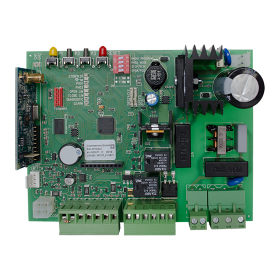
Page 5: Wiring Of Control Board
WIRING OF CONTROL BOARD The cables for the power supply and the connected equipment are routed from below into the sliding door operator through the rubber See page 5 for seal at the bottom of the control board covering. description of The control board is to be mounted with the terminal strips down terminals as shown in the picture A. -
Page 6: Wiring Diagramm
WIRING DIAGRAM 50 Ohms 230V~ +/- 10% 50Hz Ω PHO1 close/schliessen/fermer/sluiten External External back up Battery Backup battery PHO2 close/schliessen/fermer/sluiten open/öffnen/ouvrir/open TECHNICAL DATA OF CONTROL BOARD The control board is a highly modern electronic unit controlled by a microprocessor. It has all wiring facilities and functions required for safe operation. -
Page 7: Description Of Terminals
DESCRIPTION OF LEDS (LIGHT EMITTING DIODE) DESCRIPTION OF TERMINALS DESCRIPTION COLOUR STATUS Description Function STOP / 8.2 kOhms green Stop Switch 120 -230 VAC ON: Stop Active 50 - 60 Hz OFF: OK POWER SUPPLY connector (Requires wire bridge if no switch is connected) TRANSF IN 230 V to transformer... -
Page 8: Radio Transmitters
ACCESSORIES (also refer to wiring diagram) RADIO TRANSMITTERS (OPTIONAL) MODELS: TX2EV, TX4EV, TX4UNI (remote controls), 747EV (wireless keypad), 128EV (2-channel wall control) FLASHING LAMP (OPTIONAL) MODEL: FLA24-2, FLA1-LED A fl ashing lamp can be connected to the control board (Terminals: 24 V / 150 mA). It indicates gate movement. The fl ashing light should be mounted as high as possible and in good clear view. -
Page 9: Photocells
PHOTOCELLS (OPTIONAL) MODEL: 771E / 772E The photocells are for safeguarding the gate and must be used. The fi tting location depends on the gate’s design. EN12453 specifi es that a pair of photocells must be installed outside at a height of 200 mm and activated to “Close”. -
Page 10: Program Internet Gateway / Door Monitor
PROGRAM INTERNET GATEWAY myQ Using the RESET -Button on the control board 1. Connect the ethernet cable to the LiftMaster Internet Gateway and the router. 2. Connect power to the LiftMaster Internet Gateway. 3. Create an online account on the latest Liftmaster MyQ smartphone application or on www.liftmaster.eu. -
Page 11: Loop Detector
LOOP DETECTOR (OPTIONAL) DIP “OPEN/PED” must be on. Loop detectors react to metal and the most common use is for cars or trucks but not for bikes or pedestrians. Exit loop / Gate Opening Loop An exit loop is behind the gate and opens the gate when closed, keeps it open or re-opens the gate. -
Page 12: Initial Operation / Basic Setting
INITIAL OPERATION / BASIC SETTING Proceed step by step. When in doubt, start again at the beginning. Take suffi cient time to make these settings. 1. Are all components required for operation connected? Motor, photocells, safety safety edge, stop switch. 2. - Page 13 PROGRAMMIING THE TRAVEL DISTANCE AND OPERATOR FORCE 1. Gate is closed, gate position is “Close Limit”. LED „CLOSE LIM“ glows. 2. Press the button P1 until the door starts to open. (LED „LEARN“ glows) The automatic programme starts (slow speed). 3.
-
Page 14: Timer To Close (Auto-Close)
COMPLETION OF INSTALLATION / PROGRAMMING Once the travel distances are programmed, the remote controls can be programmed as well. (Refer to “Radio and Radio Programming”) 1. You can now let the gate run 2 complete cycles by pressing a key on the remote or a connected switch and observe the process. Close the gate again, WITHOUT making another setting. -
Page 15: Diagnosis Led
DIAGNOSIS LED The LED diagnostics always shows the latest upcoming issue. If several issues occur the LED diagnostics does not show them. Example: The gates’ guiding rail is soiled and the drive performs a safety reversal due to too high force. After that the photocell beam got interrupted. -
Page 16: Faqs
FAQs Pressing P1, P2 and P3 does not show any reaction DIP “RADIO PROGRAM” must be off The gate opener doesn’t respond at all; no LED is Possibly power failure. 1. Check conductor and zero conductor. 2. Check house fusing. Immediately after the gate has started moving, it Obstacle in area of gate. - Page 20 Sicherheit elektrischer Geräte für den Hausgebrauch und ähnliche Zwecke EN 60335-2-103 Besondere Anforderungen für Antriebefür Tore, Türen und Fenster Alle technischen Daten für diese Produkte werden sicher aufbewahrt und durch Chamberlain GmbH auf Anfrage den Behörden, falls erforderlich, zur Verfügung gestellt.