Advertisement
Quick Links
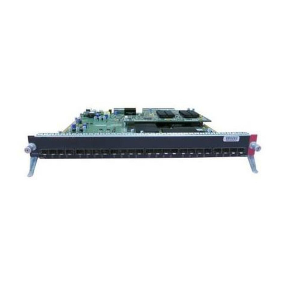
Catalyst 6500 Series Distributed Forwarding
Card 3 for WS-X67xx Modules Installation Note
This publication describes the procedures for installing and removing the Distributed Forwarding Card 3
(DFC3) daughter card on the WS-X67xx Ethernet modules. The publication covers the following
products:
•
•
•
•
•
Throughout this publication, unless otherwise noted, the term DFC3 daughter card refers to the DFC3A,
Note
DFC3B, DFC3BXL, DFC3C, and DFC3CXL daughter cards.
Contents
This publication contains these sections:
•
•
•
•
•
•
Americas Headquarters:
Cisco Systems, Inc., 170 West Tasman Drive, San Jose, CA 95134-1706 USA
WS-F6700-DFC3A(=)
WS-F6700-DFC3B(=)
WS-F6700-DFC3BXL(=)
WS-F6700-DFC3C(=)
WS-F6700-DFC3CXL(=)
Overview, page 2
Safety Overview, page 2
Required Tools and Parts, page 8
Removing the DFC3 Daughter Card, page 11
Upgrading the Ethernet Module Memory, page 19
Advertisement

Related Manuals for Cisco DFC3B


Summary of Contents for Cisco DFC3B
-
Page 1: Table Of Contents
Removing a CFC or DFC Daughter Card, page 9 • Removing the DFC3 Daughter Card, page 11 • Upgrading the Ethernet Module Memory, page 19 • Americas Headquarters: Cisco Systems, Inc., 170 West Tasman Drive, San Jose, CA 95134-1706 USA... -
Page 2: Overview
Overview Installing the DFC3B and DFC3C Daughter Cards, page 23 • Removing and Installing Ethernet Modules in the Chassis, page 34 • Attaching Your ESD Grounding Strap, page 42 • Obtaining Documentation and Submitting a Service Request, page 45 •... - Page 3 Safety Overview Statement 1071—Warning Definition Warning IMPORTANT SAFETY INSTRUCTIONS This warning symbol means danger. You are in a situation that could cause bodily injury. Before you work on any equipment, be aware of the hazards involved with electrical circuitry and be familiar with standard practices for preventing accidents.
- Page 4 Safety Overview Warnung WICHTIGE SICHERHEITSHINWEISE Dieses Warnsymbol bedeutet Gefahr. Sie befinden sich in einer Situation, die zu Verletzungen führen kann. Machen Sie sich vor der Arbeit mit Geräten mit den Gefahren elektrischer Schaltungen und den üblichen Verfahren zur Vorbeugung vor Unfällen vertraut. Suchen Sie mit der am Ende jeder Warnung angegebenen Anweisungsnummer nach der jeweiligen Übersetzung in den übersetzten Sicherheitshinweisen, die zusammen mit diesem Gerät ausgeliefert wurden.
- Page 5 Safety Overview Varning! VIKTIGA SÄKERHETSANVISNINGAR Denna varningssignal signalerar fara. Du befinner dig i en situation som kan leda till personskada. Innan du utför arbete på någon utrustning måste du vara medveten om farorna med elkretsar och känna till vanliga förfaranden för att förebygga olyckor. Använd det nummer som finns i slutet av varje varning för att hitta dess översättning i de översatta säkerhetsvarningar som medföljer denna anordning.
- Page 6 Safety Overview Aviso INSTRUÇÕES IMPORTANTES DE SEGURANÇA Este símbolo de aviso significa perigo. Você se encontra em uma situação em que há risco de lesões corporais. Antes de trabalhar com qualquer equipamento, esteja ciente dos riscos que envolvem os circuitos elétricos e familiarize-se com as práticas padrão de prevenção de acidentes. Use o número da declaração fornecido ao final de cada aviso para localizar sua tradução nos avisos de segurança traduzidos que acompanham o dispositivo.
- Page 7 Safety Overview Catalyst 6500 Series Distributed Forwarding Card 3 for WS-X67xx Modules Installation Note 78-15893-08...
-
Page 8: Required Tools And Parts
Required Tools and Parts These parts are included in the DFC3 daughter card upgrade kit: DFC3A, DFC3B, DFC3BXL, DFC3C, or DFC3CXL daughter card • Installation bracket and mounting hardware (mounts over the male standoffs at the rear of the DFC •... -
Page 9: Removing A Cfc Or Dfc Daughter Card
The MEM-XCEF720-1GB memory upgrade is required for the DFC3BXL upgrade only and is included Note as part of the DFC3BXL daughter card kit only. These tools and supplies are required to remove and install the DFC3 daughter card: Antistatic mat or foam pad to support the removed module and an antistatic bag to store the removed •... - Page 10 Removing a CFC or DFC Daughter Card Figure 1 CFC Daughter Card Installation Hardware Cap nuts (2) Card removal tabs (2) CFC daughter card Heat sinks Screws (3) WS-X5530 To unseat the CFC daughter card from the Ethernet module, hold each tab at the rear of the CFC daughter Step 5 card between your thumb and index finger, and gently press down on both tabs until the connectors are unseated.
-
Page 11: Removing The Dfc3 Daughter Card
Note 78-15893-08 Unseating the CFC Daughter Card Connectors WS-X5530 “Installing the DFC3B and DFC3C Daughter Cards” section on page Catalyst 6500 Series Distributed Forwarding Card 3 for WS-X67xx Modules Installation Note Removing a CFC or DFC Daughter Card Heat sinks... - Page 12 DFC3C or a DFC3CXL daughter card consists of 6 screws, 2 cap nuts, and 1 standoff. Catalyst 6500 Series Distributed Forwarding Card 3 for WS-X67xx Modules Installation Note for instructions. Figure Figure 3 is for a DFC3B or DFC3BXL daughter card. The “Attaching Your for removal instructions. Figure 3, use a No.1 78-15893-08...
- Page 13 Figure 3 Partially reinstall the cap nut, rotating about 3 turns so that there is a space of about 1/8 inch (3 mm) Step 6 between the bottom of the cap nut and the top of the DFC3 daughter card, as shown in nut acts as a stop when you unseat the daughter card connector so that the DFC3 daughter card does not move horizontally and cause damage to the base board.
- Page 14 Removing a CFC or DFC Daughter Card Figure 4 Appx 1/8 inch Step 7 With your left hand, lift slightly at the location shown in the DFC3 daughter card up and down with your right hand, no more than half an inch in either direction, to unseat the DFC3 daughter card from the module.
- Page 15 Figure 5 Remove the one cap nut. Step 8 Holding the DFC3 daughter card with both hands, gently lift it straight up from the module. (See Step 9 Figure 6.) Immediately place the DFC3 daughter card on an antistatic mat, antistatic foam pad, or in an antistatic bag.
- Page 16 Removing a CFC or DFC Daughter Card Figure 6 Unseat the DFC power connector Removing the DFC3 Daughter Card from WS-X6748-GE-TX Modules Equipped with a Stiffener Bracket Some early versions of the WS-X6748-GE-TX Ethernet modules have a stiffener bracket mounted across the top front part of the module.
- Page 17 Figure 7 Stiffener bracket 78-15893-08 for instructions. Removing the Installation Hardware (DFC3B/DFC3BXL Shown) (WS-X6748-GE-TX Equipped with a Front Stiffener Bracket) WS-X5530 Stiffener bracket tabs, DFC Catalyst 6500 Series Distributed Forwarding Card 3 for WS-X67xx Modules Installation Note Removing a CFC or DFC Daughter Card “Attaching Your...
- Page 18 Removing a CFC or DFC Daughter Card The two screws securing the DFC3 daughter card that pass through the front stiffener bracket Note tabs are longer than the remaining DFC installation screws. Step 6 With your left hand, lift slightly at the location shown in card up and down to unseat the daughter card from the module connectors.
-
Page 19: Upgrading The Ethernet Module Memory
Figure 9 Lift here to unseat DFC power connector Stiffener bracket Upgrading the Ethernet Module Memory When you upgrade your Ethernet module with either a DFC3BXL or DFC3CXL daughter card, you must also install a 1-GB memory upgrade (part number MEM-XCEF720-1GB) on the Ethernet module. This 1-GB memory upgrade is included with your DFC3BXL or DFC3CXL upgrade kit and installs on the Ethernet module in a small-outline dual-inline memory module (SODIMM) chip socket located underneath the DFC daughter card. - Page 20 Upgrading the Ethernet Module Memory Removing the Memory Module During this procedure, wear grounding wrist straps to avoid ESD damage to the card. Do not directly Warning touch the backplane with your hand or any metal tool, or you could shock yourself. Statement 94 To remove the existing memory module from the Ethernet module, follow these steps: Attach an ESD grounding strap to your wrist and to ground.
- Page 21 Release the two spring clips on either side of the memory module to release it from the socket. (See Step 3 Figure 11.) Figure 11 Releasing the Memory Module Spring Clips Grasp the edges of the memory module with your thumb and forefinger, and gently pull the memory Step 4 module completely out of the socket.
- Page 22 Upgrading the Ethernet Module Memory Figure 12 Handling a Memory Module Step 5 Immediately place the old memory module in an antistatic bag to protect it from ESD damage. Installing the 1-GB Memory Module Upgrade Memory modules have sensitive components that are susceptible to ESD damage. To prevent ESD Caution damage, handle memory modules by the edges only;...
- Page 23 Installing the DFC3B and DFC3C Daughter Cards This section contains two DFC3 installation procedures: Installing the DFC3B, DFC3BXL, DFC3C, and DFC3CXL Daughter Cards on Ethernet Modules • without Stiffener Brackets, page 24 Installing the DFC3B, DFC3BXL DFC3C, and DFC3CXL Daughter Cards on Ethernet Modules •...
- Page 24 Installing the DFC3B and DFC3C Daughter Cards Installing the DFC3B, DFC3BXL, DFC3C, and DFC3CXL Daughter Cards on Ethernet Modules without Stiffener Brackets During this procedure, wear grounding wrist straps to avoid ESD damage to the card. Do not directly Warning touch the backplane with your hand or any metal tool, or you could shock yourself.
- Page 25 DFC3 Daughter Card Connectors (Underside of DFC Daughter Card Shown) Connectors Figure 17 to seat the power connector. Catalyst 6500 Series Distributed Forwarding Card 3 for WS-X67xx Modules Installation Note Installing the DFC3B and DFC3C Daughter Cards Figure 16 shows...
- Page 26 Installing the DFC3B and DFC3C Daughter Cards Figure 17 Apply pressure here to seat power connector Caution Use care not to damage the connectors on the module. If you damage a connector, you will need to return the module to Cisco for repair.
- Page 27 Seating the DFC3 Daughter Card on the Module WS-X5530 Figure 20.) Catalyst 6500 Series Distributed Forwarding Card 3 for WS-X67xx Modules Installation Note Installing the DFC3B and DFC3C Daughter Cards Apply pressure to bracket. to seat DFC connectors. Do not press on heat sinks.
- Page 28 Installing the DFC3B and DFC3C Daughter Cards Figure 19 Figure 20 Catalyst 6500 Series Distributed Forwarding Card 3 for WS-X67xx Modules Installation Note Installing the Installation Hardware (DFC3B and DFC3BXL) WS-X5530 Installing the Installation Hardware (DFC3C and DFC3CXL) 78-15893-08...
- Page 29 “Removing and Installing Ethernet Modules in the Chassis” section on page 34 installation instructions. Installing the DFC3B, DFC3BXL DFC3C, and DFC3CXL Daughter Cards on Ethernet Modules Equipped with a Stiffener Bracket Some early versions of the WS-X6748-GE-TX Ethernet module have a stiffener bracket mounted across the top front part of the module.
- Page 30 Installing the DFC3B and DFC3C Daughter Cards Press down on the edge of the DFC3 daughter card (see Step 6 connector to the module power connector. Figure 21 Apply pressure to seat DFC daughter card power connector Stiffener bracket Catalyst 6500 Series Distributed Forwarding Card 3 for WS-X67xx Modules Installation Note...
- Page 31 Install the remainder of the screws and the cap nuts to fully attach the DFC3 daughter card to the module: Step 9 For the DFC3B and DFC3BXL daughter cards, install the remaining 6 screws and 2 cap nuts. (See Figure 23.)
- Page 32 Do not overtighten the installation hardware because you will damage the board. Caution Figure 23 Stiffener bracket Catalyst 6500 Series Distributed Forwarding Card 3 for WS-X67xx Modules Installation Note Installing the DFC3B and DFC3BXL Installation Hardware (WS-X6748-GE-TX Equipped with a Front Stiffener Bracket) WS-X5530 daughter card must be installed Installation bracket Stiffener bracket tabs.
- Page 33 Installing the DFC3C and DFC3CXL Installation Hardware (WS-X6748-GE-TX Equipped with a Front Stiffener Bracket) Stiffener bracket tabs. DFC daughter card must be installed underneath tabs. Catalyst 6500 Series Distributed Forwarding Card 3 for WS-X67xx Modules Installation Note Installing the DFC3B and DFC3C Daughter Cards Installation bracket for installation...
- Page 34 Removing and Installing Ethernet Modules in the Chassis Removing and Installing Ethernet Modules in the Chassis This section describes how to correctly remove and install an Ethernet module in a Catalyst 6500 series switch chassis slot. Caution During this procedure, wear grounding wrist straps to avoid ESD damage to the card. Warning Invisible laser radiation may be emitted from disconnected fibers or connectors.
- Page 35 Depending on the orientation of the slots in the chassis (horizontal or vertical), perform one of the Step 5 following two sets of substeps: Horizontal slots Place your thumbs on the left and right ejector levers located on the left and right sides of the module faceplate, and simultaneously rotate the levers outward to unseat the Ethernet module from the chassis backplane connector.
- Page 36 Removing and Installing Ethernet Modules in the Chassis Fully open both ejector levers on the Ethernet module. (See Step 3 Depending on the orientation of the slots in the chassis (horizontal or vertical), perform one of the Step 4 following two sets of substeps: Horizontal slots Position the Ethernet module in the slot.
- Page 37 Figure 25 Positioning the Module in a Horizontal Slot Chassis Insert module between slot guides EMI gasket WS -X67 48-G E-T X 48 POR Ejector lever fully extended 78-15893-08 EMI gasket INPUT OUTPU T FAIL T ETH ERN ET Catalyst 6500 Series Distributed Forwarding Card 3 for WS-X67xx Modules Installation Note Removing and Installing Ethernet Modules in the Chassis INPUT OUTPU T...
- Page 38 Removing and Installing Ethernet Modules in the Chassis Figure 26 Clearing the EMI Gasket in a Horizontal Slot Chassis Press down WS-X622 4 24 PORT 100FX WS -X6 74 8-G Figure 27 Ejector Lever Closure in a Horizontal Slot Chassis Catalyst 6500 Series Distributed Forwarding Card 3 for WS-X67xx Modules Installation Note E-T X 48 PO RT ET HE RN ET...
- Page 39 Vertical slots Position the Ethernet module in the slot. (See module carrier with the slot guides on the top and bottom of the chassis slot. Carefully slide the Ethernet module into the slot until the EMI gasket along the right edge of the module faceplate makes contact with the module in the slot adjacent to it and both ejector levers have closed to approximately 45 degrees with respect to the Ethernet module faceplate.
- Page 40 Removing and Installing Ethernet Modules in the Chassis Figure 28 Positioning the Module in a Vertical Slot Chassis STATUS INPUT OUTPUT FAIL Insert module between slot guides Catalyst 6500 Series Distributed Forwarding Card 3 for WS-X67xx Modules Installation Note Ejector lever fully extended gasket gasket...
- Page 41 Figure 29 Clearing the EMI Gasket in a Vertical Slot Chassis STATUS Press left Press left 78-15893-08 Gap between the module INPUT OUTPUT FAIL INPUT OUTPUT FAIL Catalyst 6500 Series Distributed Forwarding Card 3 for WS-X67xx Modules Installation Note Removing and Installing Ethernet Modules in the Chassis EMI gasket and the module above it 1 mm...
-
Page 42: Attaching Your Esd Grounding Strap
Attaching Your ESD Grounding Strap Figure 30 Ejector Lever Closure in a Vertical Slot Chassis STATUS All ejector levers flush with module faceplate Attaching Your ESD Grounding Strap Electrostatic discharge (ESD) damage, which can occur when modules or other FRUs are improperly handled, results in intermittent or complete failures. - Page 43 This system ground is also referred to as the network equipment building system (NEBS) Note ground. • If your chassis does not have the system ground attached, you must install the system ground lug. Refer to the online Catalyst 6500 Series Switches Installation Guide for the procedure. Note You do not need to attach a supplemental system ground wire to the system ground lug;...
- Page 44 Attaching Your ESD Grounding Strap Figure 31 ESD ground strap WS-X6 K-SUP 2-2GE CONSOL E SUPER VISOR 2 OSM-4OC 12 POS-SI 4 PORT OC-12 POS SM IR OSM-4OC 12 POS-SI 4 PORT OC-12 POS SM IR When handling modules, follow these additional guidelines: Handle carriers by available handles or edges only;...
-
Page 45: Obtaining Documentation And Submitting A Service Request
Obtaining Documentation and Submitting a Service Request Obtaining Documentation and Submitting a Service Request For information on obtaining documentation, submitting a service request, and gathering additional information, see the monthly What’s New in Cisco Product Documentation, which also lists all new and revised Cisco technical documentation, at: http://www.cisco.com/en/US/docs/general/whatsnew/whatsnew.html Subscribe to the What’s New in Cisco Product Documentation as a Really Simple Syndication (RSS) feed... - Page 46 Obtaining Documentation and Submitting a Service Request Cisco and the Cisco Logo are trademarks of Cisco Systems, Inc. and/or its affiliates in the U.S. and other countries. A listing of Cisco's trademarks can be found at www.cisco.com/go/trademarks. Third party trademarks mentioned are the property of their respective owners. The use of the word partner does not imply a partnership relationship between Cisco and any other company.