Table of Contents
Advertisement
Quick Links
M The author assumes no responsibility for any errors
or omissions that may appear in this document nor
does the author make a commitment to up
date the information contained herein.
M Third-party brands and names are the property of
their respective owners.
M Please do not remove any labels on motherboard, this
may void the warranty of this motherboard.
M Due to rapid change in technology, some of the
specifications might be out of date before publication
of this booklet.
M Before you install PCI cards, please remove the Dual
BIOS label from PCI slots if there is one.
Advertisement
Table of Contents

Related Manuals for Gigabyte GA-7DPXDW

Summary of Contents for Gigabyte GA-7DPXDW
- Page 1 M The author assumes no responsibility for any errors or omissions that may appear in this document nor does the author make a commitment to up date the information contained herein. M Third-party brands and names are the property of their respective owners.
- Page 3 Ausschlager Weg 41, 1F, 20537 Hamburg, Germany declare that the product ( description of the apparatus, system, installation to which it refers) Mother Board GA-7DPXDW is in conformity with (reference to the specification under which conformity is declared) in accordance with 89/336 EEC-EMC Directive...
- Page 4 (818) 854-9338/ (818) 854-9339 hereby declares that the product Product Name: Motherboard Model Number: GA-7DPXDW Conforms to the following specifications: FCC Part 15, Subpart B, Section 15.107(a) and Section 15.109(a), Class B Digital Device Supplementary Information: This device co mplies with part 15 of the FCC Rules . Operation is...
- Page 5 GA-7DPXDW AMD Socket A Dual Processor Motherboard USER’ S MANUAL AMD Athlon / Athlon XP / Duron Socket A Dual Processor Motherboard ™ ™ ™ Rev. 1002 12ME-7DPXDW-1002...
-
Page 6: Table Of Contents
Item Checklist ..................8 WARNING! ..................8 Chapter 1 Introduction ...............9 Summary of Features ................... 9 GA-7DPXDW Motherboard Layout ..............11 Chapter 2 Hardware Installation Process .......... 12 Step 1: Install the Central Processing Unit (CPU) ......... 13 Step1-1: CPU Speed Setup ..................13 Step1-2: CPU Installation .................. - Page 7 Table of Content Power Management Setup ................43 PnP/PCI Configurations ..................45 PC Health Status ....................47 Frequency/Voltage Control ................49 Load Fail-Safe Defaults ..................50 Load Optimized Defaults ..................51 Set Supervisor/User Password ................52 Save & Exit Setup ....................53 Exit Without Saving .....................
-
Page 8: Item Checklist
þ The GA-7DPXDW motherboard þ IDE cable x 1/ Floppy cable x 1 þ CD for motherboard driver & utility þ GA-7DPXDW user’ s manual WARNING! Computer motherboards and expansion cards contain very delicate Integrated Circuit (IC) chips. To protect them against damage from static electricity, you should follow some precautions whenever you work on your computer. -
Page 9: Chapter 1 Introduction
Form Factor — 30.4cm x 26.9cm ATX size form factor, 6 layers PCB. Motherboard — GA-7DPXDW Motherboard — Socket A Dual high performance Athlon MP System Processor AMD AthlonTM MP/AthlonTM XP/ DuronTM (K7) 128K L1 & 256K/64K L2 cache on die 200/266MHz FSB and DDR bus speeds —... - Page 10 GA-7DPXDW Motherboard — 2 Serial port (COM1 & COM2) — 4 USB ports (Rear USB x 2, Front USB x 2) — 1 IrDA connector for IR/CIR Hardware Monitor — CPU/System Fan Revolution detect — CPU/System temperature detect — System Voltage Detect —...
-
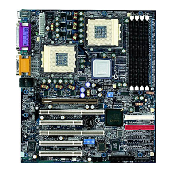
Page 11: Ga-7Dpxdw Motherboard Layout
Introduction GA-7DPXDW Motherboard Layout CPU0 FAN MS_KB CPU 0 ATX 12V AMD-762 CPU 1 CD_IN JP13 POWER FAN AC97 64PCI1 IDE4 AMD-768 PCI2 BATTERY IDE3 JP11 82550 64PCI3 IDE2 PCI4 Buzzer IDE1 Flash 20267 PCI5 SYSTEM FAN FLOPPY USB2 KEY LOCK... -
Page 12: Chapter 2 Hardware Installation Process
GA-7DPXDW Motherboard Chapter 2 Hardware Installation Process To set up your computer, you must complete the following setps: Step 1- Set system jumper (JP13) Step 2- Install the Central Processing Unit (CPU) Step 3- Install memory modules Step 4- Install expansion cards... -
Page 13: Step 1: Install The Central Processing Unit (Cpu)
Hardw are Installation Process Step 1: Install the Central Processing Unit (CPU) Step1-1: CPU Speed Setup The system bus frequency can be switched at 100/133MHz by adjusting system jumper (JP13). (The internal frequency depend on CPU.) JP13 100MHz 133MHz... -
Page 14: Step1-2: Cpu Installation
GA-7DPXDW Motherboard Step1-2: CPU Installation CPU Top View CPU Bottom View Socket Actuation Lever Pin1 indicator 2. Locate Pin 1 in the socket and look 1. Pull up the CPU socket lever for a (golden) cut edge on the CPU and up to 90-degree angle. -
Page 15: Step1-3:Cpu Heat Sink Installation
Hardw are Installation Process Step1-3:CPU Heat Sink Installation 1. Press down the CPU socket 2. Use qualified fan approved by AMD. lever and finish CPU installation. 3. Fasten the heatsink supporting-base 4. Make sure the CPU fan is onto the CPU socket on the main- plugged to the CPU fan connector, board. -
Page 16: Step 2: Install Memory Modules
GA-7DPXDW Motherboard Step 2: Install memory modules The motherboard has 4 dual inline memory module (DIMM) sockets. The BIOS will automatically detects memory type and size. To instal l the memory module, just push it vertically into t h e DIMM Slot. - Page 17 Hardw are Installation Process Registered DDR 1. The DIMM slot has a notch, so the DIMM memory module can only fit in one direction. 2. Insert the DIMM memory module verticallyinto the DIMM slot. Then push it down. 3. Close the plastic clip at both edges of theDIMM slots to lock the DIMM module.
-
Page 18: Step 3: Install Expansion Cards
GA-7DPXDW Motherboard Step 3: Install expansion cards 1. Read the related expansion card’ s instruction document before install the expansion card into the computer. 2. Remove your computer’ s chassis cover, screws and slot bracket from the computer. 3. Press the expansion card firmly into expansion slot in motherboard. -
Page 19: Step 4: Connect Ribbon Cables, Cabinet Wires, And Power Supply
Hardw are Installation Process Step 4: Connect ribbon cables, cabinet wires, and power supply Step4-1:I/O Back Panel Introduction u PS/2 Keyboard and PS/2 Mouse Connector PS/2 Mouse Connector ØThis connector supports standard PS/2 keyboard (6 pin Female) and PS/2 mouse. PS/2 Keyboard Connector (6 pin Female) v Parallel Port , Serial Ports (COM1 / COM2) - Page 20 GA-7DPXDW Motherboard w Game /MIDI Ports ØThis connector supports joystick, MIDI keyboard and other relate audio devices. Joystick/ MIDI (15 pin Female) x Audio Connectors Ø After install onboard audio driver, you may connect speaker to Line Out jack, micro phone to MIC In jack.
-
Page 21: Step4-2: Connectors Introduction
Hardw are Installation Process Step4-2: Connectors Introduction A) CPU FAN J) WOL B) (J2) POWER FAN K) IR C) IDE1~IDE4 L) CASE OPEN D) SYSTEM FAN M) KEY LOCK E) J1 N) CD IN F) FLOPPY O) ATX 12V G) USB2 P) CPU1 FAN H) BATTERY Q) ATX... - Page 22 GA-7DPXDW Motherboard A / B / D / P / R ) CPU_FAN / POWER_FAN / SYSTEM_FAN / CPU1_FAN / POWER_FAN Sense +12V/Control Ø The CPU fan connector supports Max. current up to 600 mA . Q) ATX (ATX Power)
- Page 23 Hardw are Installation Process G) USB2 K ) IR Ø Make sure the pin 1 on the IR device is aling with pin one the connector. To enable the IR/CIR function on the board, you are required to purchase an option IR/ Ø...
- Page 24 GA-7DPXDW Motherboard E) J1: F_PANEL (2x11 pins jumper) HD (IDE Hard Disk Active LED) Pin 1: LED anode(+) Pin 2: LED cathode(-) SPK (Speaker Connector) Pin 1: VCC(+) Pin 2- Pin 3: NC Pin 4: Data(-) RST (Reset Switch) Open: Normal Operation...
-
Page 25: Step4-3: Jumper Setting Introduction
Hardw are Installation Process Step4-3: Jumper Setting Introduction 1 ) JP11 5 ) J9 2 ) JP3 6 ) JP4 3 ) JP2 7 ) J8 4 ) JP1 8 ) J10... - Page 26 GA-7DPXDW Motherboard 1) JP11: Clear CMOS 5) J9: USB2 Wakeup 1-2 close: Enabled 1-2 close: Normal (Default) 2-3 close: Disabled(Default) 2-3 close: Clear CMOS 2) JP3: Promise Mode 6) JP4: Onboard LAN 1-2 close: ATA-100 1-2 close: Enabled (Default) 2-3 close: RAID (Default)
-
Page 27: Chapter 3 Bios Setup
BIOS Setup Chapter 3 BIOS Setup BIOS Setup is an overview of the BIOS Setup Program. The program that allows users to modify the basic system configuration. This type of information is stored in battery-backed CMOS RAM so that it retains the Setup information when the power is turned off. -
Page 28: The Main Menu (For Example: Bios Ver. :F2)
GA-7DPXDW Motherboard GETTING HELP Main Menu The on-line description of the highlighted setup function is displayed at the bottom of the screen. Status Page Setup Menu / Option Page Setup Menu Press F1 to pop up a small help window that describes the appropriate keys to use and the possible selections for the highlighted item. - Page 29 BIOS Setup Integrated Peripherals This setup page includes all onboard peripherals. Power Manag ement Setup This setup page includes all the items of Green function features. PnP/PCI Configurations This setup page includes all the configurations of PCI & PnP ISA resources. PC Health Status This setup page is the System auto detect Temperature, voltage, fan, speed.
-
Page 30: Standard Cmos Features
GA-7DPXDW Motherboard Standard CMOS Features CMOS Setup Utility -Copy right (C) 1984-2002 Aw ard Softw are Standard CMOS Features Date (mm:dd:y y ) Mon, Feb 21 2000 Item Help Time (hh:mm:ss) 22:31:24 Menu Lev el }IDE Primary Master Press Enter None... - Page 31 BIOS Setup C Time The times format in <hour> <minute> <second>. The time is calculated base on the 24-hour military-time clock. For example, 1 p.m. is 13:00:00. C IDE Primary Master, Slave / Secondary Master, Slave The category identifies the ty pes of hard disk from driv e C to F that has been installed in the computer.
- Page 32 GA-7DPXDW Motherboard C Floppy 3 Mode Support (for J apan Area) Normal Floppy Driv e. (Default v alue) 8Disabled 8Driv e A Driv e A is 3 mode Floppy Driv e. 8Driv e B Driv e B is 3 mode Floppy Driv e.
-
Page 33: Advanced Bios Features
BIOS Setup Advanced BIOS Features CMOS Setup Utility -Copy right (C) 1984-2002 Aw ard Softw are Adv anced BIOS Features RAID/SCSI Boot Order RAID,SCSI Item Help First Boot Dev ice Floppy Menu Lev el Second Boot Dev ice HDD-0 Third Boot Dev ice CDROM Boot Up Floppy Seek Disabled... - Page 34 GA-7DPXDW Motherboard 8USB-CDROM Select y our boot dev ice priority by USB-CDROM. Select y our boot dev ice priority by USB-HDD. 8USB-HDD Select y our boot dev ice priority by LAN. 8LAN Select y our boot dev ice priority by Disabled.
-
Page 35: Advanced Chipset Features
BIOS Setup Advanced Chipset Features CMOS Setup Utility -Copy right (C) 1984-2002 Aw ard Softw are Adv anced Chipset Features Sy stem BIOS Cacheable Disabled Item Help Video RAM Cacheable Disabled Menu Lev el AGP Aperture Size (MB) AGP ISA Aliasing Enabled AGP Fast Write Enabled... - Page 36 GA-7DPXDW Motherboard CVidio RAM Cacheable Disable this function. (Default Value) 8Disabled Enable this funct i on to get better VGA performance; w hile some brands of VGA 8Enabled must be disabled this function (e.g.ET4000W32P). C AGP Aperture Size Set AGP Aperture Size to 32 MB.
- Page 37 BIOS Setup C SDRAM ECC Setting 8Check only Detects only. 8Correct error Allows the correct i on of singl e -bit errors and the det e ction of multiple-bit errors. Detects , corrects read errors, and writes the corrected data to memory. 8Correct+scrub Disabled SDRAM ECC Setting.(Default Value) 8Disabled...
-
Page 38: Integrated Peripherals
GA-7DPXDW Motherboard Integrated Peripherals CMOS Setup Utility -Copy right (C) 1984-2002 Aw ard Softw are Integrated Peripherals IDE Read/Write Prefetch Disabled Item Help On-Chip Primary PCI IDE Enabled Menu Lev el On-Chip Secondary PCI IDE Enabled USB Host Controller Disabled øUSB Key board Support... - Page 39 BIOS Setup C IDE Read/Write Prefetch Disabled IDE Read/Write Prefetch.(Default v alue) 8Disabled Enabled IDE Read/Write Prefetch. 8Enabled C On-Chip Primary PCI IDE Disable onboard 1st channel IDE port. 8Disabled Enable onboard 1st channel IDE port. (Default Value) 8Enabled C On-Chip Second PCI IDE Disable onboard 2nd channel IDE port.
- Page 40 GA-7DPXDW Motherboard C Onboard Serial Port 1 BIOS w ill automatically setup the port 1 address. 8Auto Enable onboard Serial port 1 and address is 3F8. (Default Value) 83F8/IRQ4 Enable onboard Serial port 1 and address is 2F8. 82F8/IRQ3 Enable onboard Serial port 1 and address is 3E8.
- Page 41 BIOS Setup C UR2 Dupl ex Mode (When you set Serial Port 2 to HPSIR or ASKIR Mode) Set IR to Full mode. 8Full Set IR to Half mode.(Default Value) 8Half C Use IR Pins 8IR-Rx 2Tx 2 Enable On Board LPT port and address is 378.(Default Value) 8Rx D2,Tx D2 Enable On Board LPT port and address is 278.
- Page 42 GA-7DPXDW Motherboard CGAME Port Address Set Game Port address to 201.(Default Value) 8201 Set Game Port address to 209. 8209 Disabled Game Port 8Disabled CMidi Port Address Set Midi Port address to 330.(Default Value) 8330 Set Midi Port address to 300.
-
Page 43: Power Management Setup
BIOS Setup Power Management Setup CMOS Setup Utility -Copy right (C) 1984-2002 Aw ard Softw are Pow er Management Setup Soft-Off by PBTN Instant-off Item Help State After Pow er Failure Menu Lev el Wake-Up by PCI card Disabled RI Resume/WOL Disabled RTC Resume Disabled... - Page 44 GA-7DPXDW Motherboard C RTC Resume You can set "RTC Alarm Resume" item to enabled and key in Data/time to pow er on sy stem. Disable this function. (Default Value) 8Disabled Enable alarm function to POWER ON sy stem. 8Enabled If RTC Alarm Lead To Pow er On is Enabled.
-
Page 45: Pnp/Pci Configurations
BIOS Setup PnP/PCI Configurations CMOS Setup Utility -Copy right (C) 1984-2002 Aw ard Softw are PnP/PCI Configurations Resources Controlled By Auto Item Help øIRQ Resources Press Enter Menu Lev el PCI1/PCI5 IRQ Assignment Auto PCI2/PCI6 IRQ Assignment Auto PCI3 IRQ Assignment Auto PCI4 IRQ Assignment Auto Auto... - Page 46 GA-7DPXDW Motherboard C PCI3 IRQ Assignment Auto assign IRQ to PCI 3. (Default v alue) 8Auto Set 3,4,5,7,9,10,11,12,14,15 to PCI3. 83,4,5,7,9.,10,11,12,14,15 C PCI4 IRQ Assignment Auto assign IRQ to PCI 4. (Default v alue) 8Auto Set 3,4,5,7,9,10,11,12,14,15 to PCI4. 83,4,5,7,9.,10,11,12,14,15...
-
Page 47: Pc Health Status
BIOS Setup PC Health Status CMOS Setup Utility -Copy right (C) 1984-2002 Aw ard Softw are PC Health Status Reset Case Open Status Disabled Item Help Case Opened Menu Lev el VCORE A 1.72V VCORE B 1.74V +3.3V 3.30V 5.02V +12V 12.280 V -12V... - Page 48 GA-7DPXDW Motherboard C Current Voltage (V) VCOREA/B / 3.3V / +5V / -5V / +1 2V /-12V 8Detect sy stem’ s v oltage status automatically . C Current CPU0/1 & System Temp. (°C / °F) 8Detect CPU0/1 & Sy stem Temp. automatically.
-
Page 49: Frequency/Voltage Control
BIOS Setup Frequency/Voltage Control CMOS Setup Utility -Copy right (C) 1984-2002 Aw ard Softw are Frequency /Voltage Control ClkGen Spread Spectrum Enabled Item Help CPU Host /PCI Clock Default Menu Lev el higf: Mov e Enter:Select +/-/PU/PD:Value F10:Sav e ESC:Ex it F1:General Help F5:Prev ious Values F6:Fail-Safe Defaults F7:Optimized Defaults Figure 9: Frequency /Voltage Control C ClkGen Spread Spectrum... -
Page 50: Load Fail-Safe Defaults
GA-7DPXDW Motherboard Load Fail-Safe Defaults CMOS Setup Utility -Copy right (C) 1984-2002 Aw ard Softw are }Standard CMOS Features }Frequency /Voltage Control }Adv anced BIOS Features Load Fail-Safe Defaults }Adv anced Chipset Features Load Optimized Defaults }Integrated Peripherals Set Superv isor Passw ord... -
Page 51: Load Optimized Defaults
BIOS Setup Load Optimized Defaults CMOS Setup Utility -Copy right (C) 1984-2002 Aw ard Softw are }Standard CMOS Features }Frequency /Voltage Control }Adv anced BIOS Features Load Fail-Safe Defaults }Adv anced Chipset Features Load Optimized Defaults }Integrated Peripherals Set Superv isor Passw ord }Pow er Management Setup Set User Passw ord }PnP/PCI Configurations... -
Page 52: Set Supervisor/User Password
GA-7DPXDW Motherboard Set Supervisor/User Password CMOS Setup Utility -Copy right (C) 1984-2002 Aw ard Softw are }Standard CMOS Features }Frequency /Voltage Control }Adv anced BIOS Features Load Fail-Safe Defaults }Adv anced Chipset Features Load Optimized Defaults }Integrated Peripherals Set Superv isor Passw ord... -
Page 53: Save & Exit Setup
BIOS Setup Save & Exit Setup CMOS Setup Utility -Copy right (C) 1984-2002 Aw ard Softw are }Standard CMOS Features }Frequency /Voltage Control }Adv anced BIOS Features Load Fail-Safe Defaults }Adv anced Chipset Features Load Optimized Defaults }Integrated Peripherals Set Superv isor Passw ord }Pow er Management Setup Set User Passw ord }PnP/PCI Configurations... -
Page 54: Exit Without Saving
GA-7DPXDW Motherboard Exit Without Saving CMOS Setup Utility -Copy right (C) 1984-2002 Aw ard Softw are }Standard CMOS Features }Frequency /Voltage Control }Adv anced BIOS Features Load Fail-Safe Defaults }Adv anced Chipset Features Load Optimized Defaults }Integrated Peripherals Set Superv isor Passw ord... -
Page 55: Chapter 4 Technical Reference
Technical Reference Revision History Chapter 4 Technical Reference Block Diagram (Near AGP) (Near DDR) -
Page 56: Chapter 5 Appendix
Appendix Appendix D: Intel 82550 LAN Utility Insert the driver CD-title that came with your motherboard into your CD-ROM driver, the driver CD-title will auto start and show the installation guide. If not, please double click the CD-ROM device icon in "My computer", and execute the setup.exe. Click "Intel 82550 LAN Driver". - Page 57 GA-7DPXDW Motherboard Appendix E:AMD Power Management INF Insert the driver CD-title that came with your motherboard into your CD-ROM driver, the driver CD-title will auto start and show the installation guide. If not, please double click the CD-ROM device icon in "My computer", and execute the setup.exe.
- Page 58 Appendix Appendix F: Acronyms Acronyms Meaning ACPI Advanced Configuration and Power Interface Advanced Power Management Accelerated Graphics Port Audio Modem Riser Advanced Communications Riser BIOS Boot Specification BIOS Basic Input / Output System Central Processing Unit CMOS Complementary Metal Oxide Semiconductor CRIMM Continuity RIMM Communication and Networking Riser...
- Page 59 GA-7DPXDW Motherboard Acronyms Meaning Local Area Network Logical Block Addressing Light Emitting Diode Megahertz MIDI Musical Instrument Digital Interface Memory Translator Hub Memory Protocol Translator Network Interface Card Operating System Original Equipment Manufacturer PCI A.G.P. Controller POST Power-On Self Test...
- Page 60 Appendix Technical Support/RMA Sheet Customer/Country: Company: Phone No.: Contact Person: E-mail Add. : Model name/Lot Number: PCB revision: BIOS version: O.S./A.S.: Hardware Mfs. Model name Size: Driver/Utility: Configuration Memory Brand Video Card Audio Card CD-ROM / DVD-ROM Modem Network AMR / CNR Keyboard Mouse Power supply...