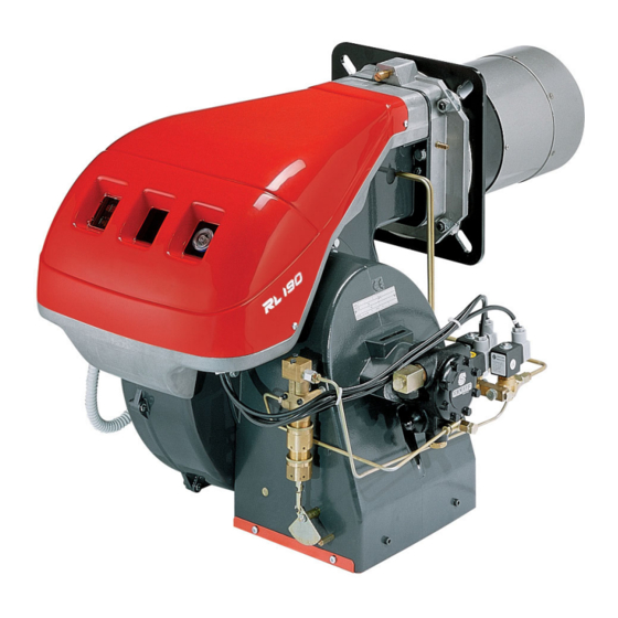
Riello RL 190 Installation, Use And Maintenance Instructions
Light oil burner
Hide thumbs
Also See for RL 190:
- Installation, use and maintenance instructions (88 pages) ,
- Two-stage operation (60 pages) ,
- Installation, use and maintenance instructions (60 pages)
Table of Contents
Advertisement
Quick Links
Installation, use and maintenance instructions
Instrucciones de instalación, uso y mantenimiento
Instruções para a instalação, uso e manutenção
Light oil burner
GB
Quemador de gasóleo
E
Queimador de gasóleo
P
Two-stage operation
Funcionamiento a dos llamas
Funcionamento a duas chamas
CODE - CÓDIGO
3475612 - 3475613
20011006 - 20011008
MODEL - MODELO
RL 190
RL 190
TYPE - TIPO
673 T1
673 T1
2916074 (6) - 03/2010
Advertisement
Table of Contents

Related Manuals for Riello RL 190


Summary of Contents for Riello RL 190
- Page 1 Queimador de gasóleo Two-stage operation Funcionamiento a dos llamas Funcionamento a duas chamas CODE - CÓDIGO MODEL - MODELO TYPE - TIPO 3475612 - 3475613 RL 190 673 T1 20011006 - 20011008 RL 190 673 T1 2916074 (6) - 03/2010...
- Page 2 UNI EN ISO 9001. management certificado según UNI EN ISO 9001. Manufacturer's Declaration Declaração de conformidade conforme a norma ISO / IEC RIELLO S.p.A. declares that the following products comply with the NOx 17050-1 limits specified by German standard “1. BImSchV 2009”. Fabricante: RIELLO S.p.A.
-
Page 3: Table Of Contents
Contents Information and general instructions............................2 Information about the instruction manual ..............................2 1.1.1 General dangers......................................2 1.1.2 Danger: live components...................................2 Guarantee and responsibility..................................3 Safety and prevention................................4 Introduction........................................4 Personnel training .....................................4 Technical description of the burner ............................5 Technical data ......................................5 3.1.1 Accessories (optional): ....................................5 3.1.2... -
Page 4: Information And General Instructions
Information and general instructions Information and general instructions Information about the instruction manual Introduction 1.1.2 Danger: live components The instruction manual supplied with the burner: This symbol indicates operations which, if not car- is an integral and essential part of the product and must not ried out correctly, lead to electric shocks with le- be separated from it;... -
Page 5: Guarantee And Responsibility
Information and general instructions Guarantee and responsibility guarantees its new products from the installation date, in accordance with the regulations in force and/or the sales con- tract. At the moment of the first start-up, check that the burner is integral and complete. Failure to observe the information given in this manual, operating negligence, incorrect installa- tion and the carrying out of non authorised modifi-... -
Page 6: Safety And Prevention
Safety and prevention Safety and prevention Introduction Personnel training burners have been designed and built in compliance The user is the person, body or company that has acquired the with current regulations and directives, applying the known tech- machine and intends to use it for the specific purpose. He is re- nical rules of safety and envisaging all the potential danger situ- sponsible for the machine and for the training of the people work- ations. -
Page 7: Technical Description Of The Burner
Technical description of the burner Technical description of the burner Technical data MODEL RL 190 CODE 3475612 - 3475613 20011006 - 20011008 OUTPUT 2nd stage 1423 - 2443 Mcal/h 1224 - 2100 DELIVERY kg/h 120 - 206 1st stage 759 - 1423... -
Page 8: Burner Description
To reset, hold the pushbutton down for between 1 and 3 seconds. Motor trip: release by pressing the pushbutton on thermal cut- out 17)(Fig. 1). 3.2.1 Weight - approximate measurements • The weight of the burner complete with its packaging is RL 190 shown in table (Tab. A) Tab. A 6074... -
Page 9: Max. Dimensions - Approximate Measurements
D1246 Fig. 3 Example: delivery 65 kg/hour: The RL 190 Model burners can work in two ways: one-stage and two-stage. diameter = 60 cm; length = 2 m. 1st stage DELIVERY must be selected within area A of the ad- Whenever the burner is operated in a much smaller commercial- jacent diagrams. -
Page 10: Installation
The output of the burner must be within the boil- er’s firing rate; WARNING A burner label that has been tampered with, re- RIELLO S.p.A. 0036 I• 37045 Legnago (VR) moved or is missing, along with anything else that prevents the definite identification of the burner Fig. -
Page 11: Boiler Plate
Installation Boiler plate Drill the combustion chamber locking plate as shown in (Fig. 6). The position of the threaded holes can be marked using the ther- mal screen supplied with the burner. RL 190 325-368 M 16 Fig. 6 D455... -
Page 12: Choice Of Nozzles For 1St And 2Nd Stage
Installation Choice of nozzles for 1st and 2nd stage Both nozzles must be chosen from among those listed in table Example (Tab. B). Boiler output = 1630 kW - efficiency 90 % The first nozzle determines the delivery of the burner in the 1st Output required by the burner = stage. -
Page 13: Nozzle Assembly
Installation Nozzle assembly At this stage of installation the burner is still disassembled from the blast tube; it is therefore possible to fit the nozzle with the box spanner 1) (Fig. 8) (16 mm), after having removed the plastic plugs 2) (Fig. 8), fitting the spanner through the central hole in the flame stability disk. -
Page 14: Combustion Head Setting
5) (Fig. 10, pag. 11). Example: The RL 190 Model with two 18 GPH nozzles and 12 bar pump pressure. Find the delivery of the two 18 GPH nozzles in (Tab. A, pag. 6): Fig. -
Page 15: Electrical System
Do not invert the neutral with the phase in the electrical supply line. Any inversion would cause a lockout due to firing failure. The RL 190 burners have been type-approved for intermittent operation. This means they should compulsorily be stopped at least once every 24 hours to enable the control box to perform checks of its own start-up efficiency. -
Page 16: Electrical System (Factory Set)
Electrical system Electrical system (factory set) Fig. 14 D3229 Key to wiring diagram (Fig. 14) 5.1.1 Electrical connections - Motor contactor - Photoresistor - Switch: burner off - on - Switch: 1st - 2nd stage operation - Terminal strip - Fan motor RMO88.53A2 - Control box - Thermal cut-out... - Page 17 Electrical system RL 190 Models electrical connection three-phase 230/400 V power supply with neutral phase wire. D3239 Fig. 16 RL 190 Model Thermal relay adjustment RL 190 - 230 V 16 A 230 V 400 V RL 190 - 400 V...
-
Page 18: Hydraulic System
Hydraulic system Hydraulic system Fuel supply The loop circuit A loop circuit consists of a loop of piping departing from and re- turning to the tank with an auxiliary pump that circulates the fuel under pressure. A branch connection from the loop goes to feed the burner. -
Page 19: Hydraulic Connections
Hydraulic system Hydraulic connections The pumps are equipped with a by-pass that connects return line with suction line. The pumps are installed on the burner with the by-pass closed by screw 6) (Fig. 23 pag. 19). It is therefore necessary to connect both hoses to the pump. The pump will break down immediately if it is run with the return line closed and the by-pass screw inserted. -
Page 20: Burner Calibration
Burner calibration Burner calibration Firing Check the correct working of the adjustment, com- Burner Stage mand and safety devices. WARNING Set switch 1) (Fig. 20) to "ON". During the first firing, during the passage from the 1st to the 2nd Fig.