Table of Contents
Advertisement
Quick Links
Advertisement
Table of Contents

Related Manuals for JBL SRX900 Series


Summary of Contents for JBL SRX900 Series
- Page 1 Rigging Manual...
- Page 2 Rigging Manual GENERAL INFORMATION SRX900 Series - Rigging Manual Document Number: 1000365022 Version: A - EN Distribution Date: May 10, 2022 Copyright © 2022 by HARMAN International; all rights reserved JBL PROFESSIONAL 8500 Balboa Blvd Northridge, CA 91329...
-
Page 3: Table Of Contents
Rigging Manual T ABLE OF CONTENTS 1 - SAFETY . . . . . . . . . . . . . . . . . . . . . . . . . . . . . . . . . . . . . . . . . . . . . . . . . . . . . . . . . . . . . . . . . . . . . . . . . . . . . . . . . . . . . . . . . . . . . . . . . 5 1.1 Safety Instructions . - Page 4 Rigging Manual 8.3 Suspend the First Stack ................30 8.4 Attach the Next Stack .
-
Page 5: Safety
11. Contact JBL Professional for advanced servicing issues. 12. CAUTION - DO NOT PERFORM ANY SERVICING UNLESS YOU ARE QUALIFIED TO DO SO. -
Page 6: Are You New To Rigging
For all other hardware and fittings, refer to the hardware manufacturer’s inspection and maintenance guidelines for process . JBL is not responsible for the application of its products for any purpose or the misuse of this information for any purpose. Furthermore, JBL is not responsible for the abuse of its products caused by avoiding compliance with inspection and maintenance procedures or any other abuse. -
Page 7: Symbols
1.8 RESOURCES AND DOCUMENT A TION Several resources are available to SRX900 Series owners to illustrate proper and safe use of the equipment. Below is an overview of what is available and a brief description of each resource: USER MANUAL: This document focuses on the electromechanical aspects of the system, including amplification, wiring, speaker pre- sets, tuning, and optimization. -
Page 8: Mechanical Limits
DGUV regulation 17 (BGV-C1) for a minimum safety factor of 4:1. Minimum safety factor requirements for suspended arrays are often set by local regulations. Use JBL Line Array Calculator 3 software to check mechanical limits and ensure compliance with local regulations. -
Page 9: System Components
Rigging Manual 3 - SYSTEM COMPONENTS SRX906LA | Line Array Element SRX910LA | Line Array Element SRX918S | Subwoofer SRX928S | Subwoofer SRX906LA AF | Array Frame SRX910LA AF | Array Frame SRX906LA CASE SRX910LA VT CVR SRX910LA VT | Vertical Transport... - Page 10 Rigging Manual SRX900LA PB | Pull Back SRX906LA BP | Base Plate SRX910LA BP | Base Plate VTX PM | Pole Mount SRX900 RC | Rain Cover ACK1 | Accessory Caster Kit SRX928S CVR SRX918S CVR...
-
Page 11: Software
4.1 LINE ARRA Y CALCULA TOR 3 Line Array Calculator 3 acoustical prediction software is used for the design and mechanical validation of SRX900 Series line array systems. Using LAC-3 is a three-step process. First, venue dimensions are defined using either X/Y/Z coordinates or the fast distance/ angle method. -
Page 12: Suspended Arrays
Rigging Manual 4.2 SUSPENDED ARRA YS Line Array Calculator checks the mechanical safety of suspended arrays and takes into consideration all variables that can affect the mechanical safety and safety factors. The software validates the mechanical stresses on the enclosures, speaker rigging components, and all accessories used as part of an array. -
Page 13: Ground-Stacked Arrays
This message is presented when the specified array design exceeds the mechanical limits set by the JBL team for the speakers or selected accessories. Array designs that trigger this message should not be used under any conditions, as they can lead to hardware damage and/or injury. -
Page 14: Rigging System Overview
5 - RIGGING SYSTEM OVERVIEW SRX900 Series line array cabinets include an intuitive three-point rigging system. Angles are preselected while the system is still on the ground using the link bar, which extends vertically to the cabinet above. When an array is suspended, angles are locked using the stop pin. -
Page 15: Angle Selection
LINK BAR INDICATOR When selecting angles on a stack of SRX900 Series cabinets, always start at the top cabinet and work down to the lowest. Angles are selected while SRX900 Series cabinets are on the carts and resting on the ground. Since the rigging mechanism is not under load when the system is on the ground, the link bar can be moved freely to the desired position. -
Page 16: Transportation
6 - TRANSPORT A TION Each component in the SRX900 Series has a convenient and efficient transportation system. The SRX906LA and SRX910LA are both transported in stacks of four cabinets with their angles fully collapsed. The SRX906LA cabinets ride inside of a rugged road case and the SRX910LA cabinets travel on a vertical transport cart. -
Page 17: Installing Cabinets On The Case Or Vt
Rigging Manual 6.1 INST ALLING CABINETS ON THE CASE OR VT Both the SRX9xxLA cabinets attach to their respective transport carts the same way, the following set of instructions is valid for both the SRX906LA with the SRX906LA Case as well as the SRX910LA with the SRX910LA VT. STEPS: •... - Page 18 Rigging Manual STEPS (Continued): • Prepare the next enclosure by setting the link bar to the 12˚ position, storing the stop pin in the handle, removing the link pin and the two front pins. • Lower the next SRX900LA cabinet onto the first enclosure and secure the two cabinets together at the front using the pins. •...
-
Page 19: Installing The Vt-Top
Rigging Manual 6.2 INST ALLING THE VT -TOP The VT-TOP connects to the top cabinet of an SRX910LA stack to form a robust and defined footprint that stabilizes the carts during transportation. The flat top allows other gear to be stacked on top of SRX910LA arrays traveling on SRX910LA VT carts for a more efficient truck pack. -
Page 20: Storing The Srx910La Vt
Rigging Manual 6.3 STORING THE SRX910LA VT Once an SRX910LA stack has been deployed, the VT-TOP can attach to the SRX910LA VT for storage. Several carts can be stacked together for storage. STEPS: • Pin the rear attachment point of the VT-TOP into the storage position. •... -
Page 21: Stacking The Srx910La Vt
Rigging Manual 6.4 ST ACKING THE SRX910LA VT When the SRX910LA VT and VT-TOP are attached, several assemblies can be stacked together for storage. -
Page 22: Installing The Ack1
Rigging Manual 6.5 INST ALLING THE ACK1 STEPS: • Remove the four bolts that were pre-installed into the threaded M10 nuts. • Using the included hardware, place one split lock washer and then one washer onto each of the four bolts. •... -
Page 23: Array Frames
7 - ARRA Y FRAMES The SRX906LA and SRX910LA AF Array Frames are used for suspending SRX900 Series arrays. Although different in size, the two frames are functionally identical. The array frames were designed to work with single-point and front-back suspension methods. For single-point applications, the array frame can be used in conjunction with the VTX RC500 rotating clamp, allowing smaller arrays to be suspended from standard size trusses or pipes. -
Page 24: Attaching The Extension Bar To The Spreader Bar
Rigging Manual 7.2 A TT ACHING THE EXTENSION BAR TO THE SPREADER BAR The extension bar includes two pins for attaching to the spreader bar. An additional pin attached to the spreader bar is used in conjunc- tion with one of the pins attached to the extension bar to create the completed array frame assembly. STEPS: •... -
Page 25: Array Frame Attachment Options
The example below shows how the real and “virtual” positions are spaced across the extension bar. TIP: Refer to JBL Line Array Calculator 3 software to determine the best shackle position and attachment combination to achieve the required array angle. -
Page 26: Extension Bar Positioning
Rigging Manual 7.4 EXTENSION BAR POSITIONING When the extension bar is attached to the array frame in its normal orientation, it extends towards the rear of the array, permitting the maximum possible downtilt for the array. The extension bar also can be attached in a reversed position, which provides the maximum possible uptilt. -
Page 27: Installing The Laser Bracket
Rigging Manual 7.5 INST ALLING THE LASER BRACKET The array frames includes a mounting bracket that enables installing a third-party laser inclinometer on the array frame. The included laser bracket was designed to work with various industry standard systems. STEPS: •... -
Page 28: Deploying Arrays
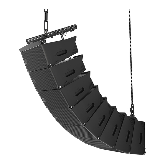
Rigging Manual 8 - DEPLOYING ARRA YS Suspending arrays is a simple and straightforward process. Carefully follow the steps in this chapter to correctly and safely suspend an array. Although an SRX910LA array is pictured in the chapter, the process is the same for both SRX906LA and SRX910LA systems. 8.1 SET THE ANGLES FOR THE FIRST SET OF CABINETS STEPS: •... -
Page 29: Attaching The Array Frame
Rigging Manual 8.2 A TT ACHING THE ARRA Y FRAME After setting the angles of the first stack of cabinets in an array, follow the steps below for attaching the array frame. For easiest attach- ment, separate the spreader bar from the extension bar. STEPS: •... -
Page 30: Suspend The First Stack
Rigging Manual 8.3 SUSPEND THE FIRST ST ACK STEPS: • Check to make sure that all cabinet pins are properly installed. Engage the hoist to lift the array off the ground. As the hoist lifts, each cabinet will expand to the correct angle. •... - Page 31 Rigging Manual STEPS (Continued): • Disconnect the Vertical Transporter or Case bottom by removing the front two pins, allowing the front wheels of the cart to touch the ground. • Remove the bottom STOP Pin and place it in the handle. •...
-
Page 32: Attach The Next Stack
Rigging Manual 8.4 A TT ACH THE NEXT ST ACK STEPS: Follow the steps in Section 9 .1 Set the Angles for the First Set of Cabinets to set the angles of the next stack of SRX9xxLA • cabinets. • Raise the suspended cluster and align the next set of cabinets below. - Page 33 Rigging Manual STEPS (Continued): • Use the electric hoist to raise the array. Be aware that the lower cluster may swing forward as it lifts off the ground. • Insert the stop pins of the top three cabinets of the lower stack. •...
-
Page 34: Repeat Until Completed
Rigging Manual 8.5 REPEA T UNTIL COMPLETED Repeat the steps in Section 8 .4 until the entire array has been assembled. -
Page 35: Disassembling An Array
Rigging Manual 9 - DISASSEMBLING AN ARRA Y Follow the steps in this chapter to safely disassemble an array. Although an SRX910LA is pictured in the chapter, the same steps should be followed for an SRX906LA array. 9.1 LOWER THE ARRA Y AND REMOVE THE STOP PINS STEPS: •... -
Page 36: Collapse The Array And Move The Pins To The Storage Position
Rigging Manual 9.2 COLLAPSE THE ARRA Y AND MOVE THE PINS TO THE STORAGE POSITION STEPS: • Lower the array until the front wheels touch the ground. The array should start to roll backwards and, as the array is lowered, the cabinet-to-cabinet angles of the bottom five cabinets will close to the 12˚... -
Page 37: Repeat Steps To Disconnect The Next Four Cabinets
Rigging Manual 9.3 REPEA T STEPS TO DISCONNECT THE NEXT FOUR CABINETS Repeat the previous steps to disconnect and store the next four cabinets of the array. - Page 38 Rigging Manual...
-
Page 39: The Srx900La Pb Pull-Back
Rigging Manual 10 - THE SRX900LA PB PULL-BACK The SRX900LA PB is a pull-back attachment for configurations requiring a significant amount of downtilt. With the array frame connect- ed to the primary suspension point at the top of the array, the SRX900LA PB connects to the bottom of the array and is lifted by a second motor point at the rear of the array. -
Page 40: When To Use A Pull-Back
Rigging Manual 10.2 WHEN TO USE A PULL-BACK The use of a pull-back is common when the center of gravity (CoG) of an array falls outside the footprint of the array frame. Typically, long curved arrays with a large downtilt qualify for this condition. When this occurs, LAC-3 displays an error to indicate that the array frame alone cannot achieve the down angle needed for the design (Example 1 - No pull-back). -
Page 41: Base Plates
When not used with subwoofers, M10 through-holes can be used to permanently attach an array to other support structures. The base plates include one 50 mm wide (2 in) notch on each side for easy use with ratchet straps. Configurations and load conditions for using a Base Plate can be obtained using JBL’s LAC-3 software 11.1 BASE PLA TE OVERVIEW 2”... -
Page 42: Base Plate Storage Position
The base plate angle selection plate includes nine pin positions, allowing for a range of angles from -15 to +5 degrees in 2.5-degree steps. This facilitates selection of the most appropriate position for establishing the required array down angle. JBL Line Array Calculator 3 software is used to determine the best position and check array safety. -
Page 43: Assembling Ground-Stacked Arrays
The base plate connects to the subwoof- ers using the included M20 knob. SRX900 Series cabinets connect to the base plate using the cabinet’s front pins, and the link pin in the rear. - Page 44 Rigging Manual STEPS (Continued): • Remove the link pin and install the stop pin into the angle selection plate of the first SRX9xxLA cabinet. • Place the first SRX9xxLA cabinet onto the base plate and pin the front two corners using the attached pins. •...
- Page 45 Rigging Manual STEPS (Continued): • Select the desired cabinet-to-cabinet angle for the first SRX9xxLA enclosure and extend the link bar to that angle. Pin the link bar with the angle selection pin in the corresponding hole of the angle selection plate. •...
-
Page 46: Ground Stack Examples
Rigging Manual 11.5 GROUND ST ACK EXAMPLES SRX906LA SRX906LA BP SRX918S SRX910LA SRX910LA BP SRX928S... -
Page 47: Attaching The Base Plate Onto A Structure
Rigging Manual 11.6 A TT ACHING THE BASE PLA TE ONTO A STRUCTURE The base plate can be permanently attached to a structure like a stage or platform using its three M10 through-holes. This is especially useful for permanent installations or other fixed applications where a ground-stacked SRX9xxLA system is needed, but not often moved. In such situations, the base plate is permanently attached to the structure and subwoofers are not used beneath the array. -
Page 48: Pole Mounting The Srx906La Bp
Adapter. This pole mount accessory attaches directly to the bottom of the Base Plate using two included thumb screws and enables the user to safely stack two SRX906LA cabinets at an elevated height, either on top of a compatible SRX900 Series subwoofer or on top of a tripod pole. -
Page 49: Contact Information
+1 (844) 776-4899 www.jblpro.com PROFESSIONAL CONT ACTS, OUTSIDE THE U.S.A.: Contact the JBL Professional Distributor in your area. A complete list of JBL Professional international distributors is provided at our U.S.A. website: www.jblpro.com HARMAN Professional EMEA HARMAN Professional APAC... - Page 50 Rigging Manual...