Maytag MGR7661WW Installation Instructions Manual
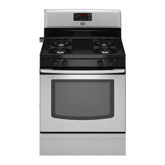
30" (76.2 cm) freestanding gas ranges
Hide thumbs
Also See for MGR7661WW:
- User instructions (12 pages) ,
- Installation instructions manual (20 pages)
Table of Contents
Advertisement
30" (76.2 CM) FREESTANDING GAS RANGES
IMPORTANT:
Save for local inspector's use.
Installer: Leave installation instructions with the homeowner.
Homeowner: Keep installation instructions for future reference.
W10403809B
INSTALLATION INSTRUCTIONS
Table of Contents
RANGE SAFETY............................................................................. 2
INSTALLATION REQUIREMENTS ............................................... 3
Tools and Parts............................................................................ 3
Location Requirements ............................................................... 3
Electrical Requirements............................................................... 5
Gas Supply Requirements .......................................................... 5
INSTALLATION INSTRUCTIONS ................................................. 7
Unpack Range............................................................................. 7
Install Anti-Tip Bracket ................................................................ 7
Make Gas Connection................................................................. 8
Verify Anti-Tip Bracket Is Installed and Engaged ....................... 9
Level Range ............................................................................... 10
Electronic Ignition System......................................................... 10
Warming Drawer or Premium Storage Drawer ......................... 12
Storage Drawer.......................................................................... 12
Oven Door.................................................................................. 13
Complete Installation................................................................. 13
GAS CONVERSIONS ................................................................... 14
LP Gas Conversion.................................................................... 14
Natural Gas Conversion ............................................................ 17
Advertisement
Table of Contents

Related Manuals for Maytag MGR7661WW

Summary of Contents for Maytag MGR7661WW
-
Page 1: Table Of Contents
INSTALLATION INSTRUCTIONS 30" (76.2 CM) FREESTANDING GAS RANGES RANGE SAFETY... 2 INSTALLATION REQUIREMENTS ... 3 Tools and Parts... 3 Location Requirements ... 3 Electrical Requirements... 5 Gas Supply Requirements ... 5 INSTALLATION INSTRUCTIONS ... 7 Unpack Range... 7 Install Anti-Tip Bracket ... 7 Make Gas Connection... -
Page 2: Range Safety
Your safety and the safety of others are very important. We have provided many important safety messages in this manual and on your appliance. Always read and obey all safety messages. This is the safety alert symbol. This symbol alerts you to potential hazards that can kill or hurt you and others. All safety messages will follow the safety alert symbol and either the word “DANGER”... -
Page 3: Installation Requirements
A child or adult can tip the range and be killed. Install anti-tip bracket to floor or wall per installation instructions. Slide range back so rear range foot is engaged in the slot of the anti-tip bracket. Re-engage anti-tip bracket if range is moved. Do not operate range without anti-tip bracket installed and engaged. - Page 4 Mobile Home - Additional Installation Requirements The installation of this range must conform to the Manufactured Home Construction and Safety Standard, Title 24 CFR, Part 3280 (formerly the Federal Standard for Mobile Home Construction and Safety, Title 24, HUD Part 280). When such standard is not applicable, use the Standard for Manufactured Home Installations, ANSI A225.1/NFPA 501A or with local codes.
-
Page 5: Electrical Requirements
Electrical Requirements WARNING Electrical Shock Hazard Plug into a grounded 3 prong outlet. Do not remove ground prong. Do not use an adapter. Do not use an extension cord. Failure to follow these instructions can result in death, fire, or electrical shock. IMPORTANT: The range must be electrically grounded in accordance with local codes and ordinances, or in the absence of local codes, with the National Electrical Code, ANSI/NFPA 70... - Page 6 Gas Supply Line Provide a gas supply line of ¾" (1.9 cm) rigid pipe to the range location. A smaller size pipe on longer runs may result in insufficient gas supply. With LP gas, piping or tubing size can be ½" (1.3 cm) minimum. Usually, LP gas suppliers determine the size and materials used in the system.
-
Page 7: Installation Instructions
INSTALLATION INSTRUCTIONS Unpack Range WARNING Excessive Weight Hazard Use two or more people to move and install range. Failure to do so can result in back or other injury. 1. Remove shipping materials, tape and film from range. 2. Remove oven racks and parts package from inside oven. 3. -
Page 8: Make Gas Connection
Floor Mounting Rear position Front position Wall Mounting 5. Using the Phillips screwdriver, mount anti-tip bracket to the wall or floor with the two #12 x 1 " screws provided. 6. Move range close enough to opening to allow for final gas and electrical connections. -
Page 9: Verify Anti-Tip Bracket Is Installed And Engaged
3. Use a " combination wrench and channel lock pliers to attach the flexible connector to the adapters. Check that connector is not kinked. A. Gas pressure regulator E. Manual gas shutoff valve B. Use pipe-joint compound. F. ½" or ¾" gas pipe C. -
Page 10: Level Range
IMPORTANT: If there is a snapping or popping sound when lifting the range, the range may not be fully engaged in the bracket. Check to see if there are obstructions keeping the range from sliding to the wall or keeping the range foot from sliding into the bracket. - Page 11 If the “low” flame needs to be adjusted: A. Control knob stem B. Screwdriver C. Pliers 1. Light 1 burner and turn to lowest setting. 2. Remove the control knob. Hold the knob stem with a pair of pliers. Use a small flat- blade screwdriver to turn the screw located in the center of the control knob stem until the flame is the proper size.
-
Page 12: Warming Drawer Or Premium Storage Drawer
If flame needs to be adjusted: 1. Loosen the lock screw on the air shutter located at the rear of the broil burner. 2. Adjust the air shutter as needed. 3. Tighten lock screw. A. Lock screw B. Air shutter 4. -
Page 13: Oven Door
To Replace: 1. Lift up the front of the drawer and place the rear of the drawer inside the range so that the drawer stop notch is behind the drawer glide. 2. Lower the drawer so that the edge of the slide rail drops into the slot in the drawer glide. -
Page 14: Gas Conversions
Gas conversions from Natural gas to LP gas or from LP gas to Natural gas must be done by a qualified installer. WARNING Explosion Hazard Use a new CSA International approved gas supply line. Install a shut-off valve. Securely tighten all gas connections. If connected to LP, have a qualified person make sure gas pressure does not exceed 14"... - Page 15 3. Remove plastic cover from gas pressure regulator cap. 4. Turn gas pressure regulator cap counterclockwise with a " combination wrench to remove. NOTE: Do not remove the spring beneath the cap. Side view before Side view after A. Plastic cover B.
-
Page 16: To Convert Oven Broil Burner
To Convert Oven Bake Burner (Natural Gas to LP Gas) 1. Remove the oven racks. 2. Remove 2 screws at the rear of the oven bottom. 3. Lift the rear of the oven bottom up and back until the front of the panel is away from the front frame. -
Page 17: Natural Gas Conversion
4. Replace the “53” hood with a “090” hood. Install the LP gas broiler burner orifice hood, turning it clockwise until snug. IMPORTANT: Do not overtighten. A. Orifice hood 5. Place the broil burner on the broil burner orifice hood and insert the broil burner ceramic igniter in the hole in the rear of the oven. - Page 18 4. Turn gas pressure regulator cap counterclockwise with a " combination wrench to remove. NOTE: Do not remove the spring beneath the cap. Side view before Side view after A. Plastic cover B. Gas pressure regulator cap with hollow end facing out C.
- Page 19 4. Remove 2 screws from the front tabs of the flame spreader. Lift front of the flame spreader and pull forward to remove tabs from rear of oven and set it aside on a covered surface. A. Screws B. Flame spreader 5.
- Page 20 5. Place the broil burner on the broil burner orifice hood and insert the broil burner ceramic igniter in the hole in the rear of the oven. 6. Position the broil burner against the top of the oven and attach it with 2 screws. 7.