Table of Contents
Advertisement
Quick Links
We advise you to read this manual carefully, as it contains all the instructions for maintaining
the appliance's aesthetic and functional qualities.
For further information on the product: www.smeg.com
Table of contents
ORIGINAL INSTRUCTIONS
4
4
8
8
9
9
9
10
10
11
11
12
12
13
14
15
15
17
17
18
20
20
23
23
23
24
25
27
29
31
31
34
36
42
43
3
Advertisement
Table of Contents

Related Manuals for Smeg SSA60MX9


Summary of Contents for Smeg SSA60MX9
-
Page 1: Table Of Contents
5.3 Positioning 5.4 Electrical connection 5.5 Instructions for the installer ORIGINAL INSTRUCTIONS We advise you to read this manual carefully, as it contains all the instructions for maintaining the appliance’s aesthetic and functional qualities. For further information on the product: www.smeg.com... -
Page 2: Instructions
Instructions 1 Instructions • Cleaning and maintenance must not be carried out by 1.1 General safety instructions unsupervised children. Risk of personal injury • Make sure that the flame- spreader crowns are correctly • During use the appliance and positioned in their seats with its accessible parts become their respective burner caps. - Page 3 Instructions • Keep the oven door closed • Before any operation on the during cooking. appliance (installation, maintenance, positioning or • If you need to move food or at movement) always wear PPM. the end of cooking, open the door 5 cm for a few seconds, •...
- Page 4 Instructions • Do not sit on the appliance. • Remove all trays and racks which are not required during • Racks and trays should be cooking. inserted as far as they will go into the side guides. The • Do not cover the bottom of the mechanical safety locks that oven cavity with aluminium or prevent them from being...
- Page 5 Instructions • Do not put empty pans or frying Installation pans on switched on cooking • THIS APPLIANCE MUST NOT zones. BE INSTALLED IN A BOAT OR • Do not use rough or abrasive CARAVAN. materials or sharp metal • This appliance must not be scrapers.
-
Page 6: Manufacturer Liability
Instructions • The adjustment conditions for system safety standards. this appliance are shown on • Use cables withstanding a the gas setting label. temperature of at least 90 °C. • Have the gas connection • The tightening torque of the performed by authorised staff. -
Page 7: Identification Plate
Instructions considered inappropriate. To dispose of the appliance: • Cut the power supply cable and • The appliance is not designed remove it along with the plug. to operate with external timers Power voltage or with remote-control systems. Danger of electrocution 1.4 Identification plate •... -
Page 8: How To Read The User Manual
Instructions 1.7 How to read the user manual 1.8 To save energy This user manual uses the following reading • Only preheat the appliance if the conventions: recipe requires you to do so. Instructions • Unless otherwise indicated on the package, defrost frozen foods General information on this user manual, on safety and final... -
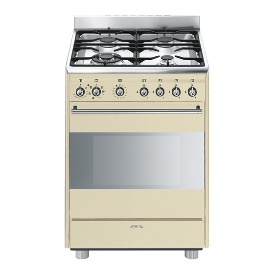
Page 9: Description
Description 2 Description 2.1 General Description 1 Upstand 5 Seal 2 Cooking hob 6 Door 3 Control panel 7 Fan 4 Light bulb 8 Storage compartment Rack/tray support frames... -
Page 10: Cooking Hob
Description 2.2 Cooking hob AUX = Auxiliary burner UR-3c = Ultra-rapid burner SR = Semi-rapid burner 2.3 Control panel 1 Temperature knob 3 Function knob This knob allows you to select the cooking The oven’s various functions are suitable for temperature. -
Page 11: Other Parts
Description 5 Hob burner knobs Cooling fan Used for lighting and adjusting the hob burners. Press and turn the knobs anti- clockwise to in order to light the relative burners. Turn the knobs to the zone between the maximum and minimum setting to adjust the flame. -
Page 12: Available Accessories
Description Interior lighting Deep tray The appliance’s interior lighting comes on: • when the door is opened; • when any function is selected, apart from function. when the door is open, it is not possible to turn off the interior lighting. -
Page 13: Use
3 Use High temperature inside the storage compartment 3.1 Instructions Danger of burns High temperature inside the oven • Do not open the storage compartment during use when the appliance is on and still hot. Danger of burns • The items inside the storage compartment could be very hot after •... - Page 14 Malfunctions High temperature inside the storage compartment Any of the following indicate a malfunction and you should contact a service centre: Danger of fire or explosion • Yellowing of the burner plate. • Do not spray any spray product near the •...
-
Page 15: Using The Accessories
3.2 Using the accessories 3.3 Using the hob All the appliance’s control and monitoring Racks and trays devices are located together on the front Racks and trays have to be inserted into the panel. The burner controlled by each knob side guides until they come to a complete is shown next to the knob. -
Page 16: Using The Oven
Correct positioning of the flame- 3.4 Using the oven spreader crowns and burner caps Switching on the oven Before lighting the hob burners, make sure To switch the oven on: that the flame-spreader crowns are correctly positioned in their seats with their respective 1. - Page 17 Grill Fan with round heating element The heat coming from the grill The combination of the fan and the element gives perfect grilling results round heating element above all for thin and medium (incorporated in the rear of the thickness meat and, in combination oven) allows you to cook different with the rotisserie (where fitted), foods on several levels, as long as...
-
Page 18: Using The Storage Compartment
3.5 Using the storage compartment Advice for cooking meat The storage compartment is at the bottom of • Cooking times vary according to the the cooker. To open it, pull the handle thickness and quality of the food and to towards you. - Page 19 • To check whether the dessert is cooked right through: At the end of the cooking time, put a toothpick into the highest point of the dessert. If the dough does not stick to the toothpick, the dessert is cooked. •...
- Page 20 Cooking information table Weight Temperature Food Function Shelf Time (minutes) (kg) (°C) Lasagne 3 - 4 Static 220 - 230 45 - 50 Pasta bake 3 - 4 Static 220 - 230 45 - 50 Roasted veal Turbo/Round 180 - 190 90 - 100 Pork loin Turbo/Round...
-
Page 21: Cleaning And Maintenance
Cleaning and maintenance 4 Cleaning and maintenance Ordinary daily cleaning Always use specific products only that do 4.1 Instructions not contain abrasives or chlorine-based acids. Improper use Pour the product onto a damp cloth and Risk of damage to surfaces wipe the surface, rinse thoroughly and dry with a soft cloth or a microfibre cloth. -
Page 22: Cleaning The Hob
Cleaning and maintenance 4.3 Cleaning the hob Flame-spreader crowns and burner caps For easier cleaning, the flame-spreader Knobs crowns and the burner caps can be removed. Wash them in hot water and non- Do not use aggressive products abrasive detergent. Carefully remove any containing alcohol or products for encrustation, then wait until they are cleaning steel and glass when... -
Page 23: Cleaning The Door
Cleaning and maintenance 2. Grasp the door on both sides with both Knobs hands, lift it forming an angle of around Do not use aggressive products 30° and remove it. containing alcohol or products for cleaning steel and glass when cleaning the knobs, as these products could cause permanent damage. - Page 24 Cleaning and maintenance Cleaning the door glazing 4. Clean the external glass pane and the previously removed panes. Use The door glazing should always be kept absorbent kitchen roll. In case of thoroughly clean. Use absorbent kitchen stubborn dirt, wash with a damp sponge roll.
-
Page 25: Cleaning The Oven Cavity
Cleaning and maintenance 4.5 Cleaning the oven cavity Cleaning of racks and trays For the best oven cavity upkeep, clean it Clean the racks and trays with warm water regularly after having allowed it to cool. and non-abrasive detergents. Carefully rinse and dry damp parts. - Page 26 Cleaning and maintenance Vapour Clean Vapor Clean is an assisted cleaning procedure which facilitates the removal of dirt. Thanks to this process, it is possible to clean the inside of the oven very easily. The dirt residues are softened by the heat and water vapour for easier removal afterwards.
-
Page 27: Extraordinary Maintenance
Cleaning and maintenance Vapor Clean cycle setting 4.6 Extraordinary maintenance Installing and removing the seal 1. Turn the function knob to the symbol and the temperature knob to the symbol To remove the seal: • Unhook the clips in the 4 corners then pull the seal outwards. - Page 28 Cleaning and maintenance Replacing the internal light bulb 4. Slide out and remove the light bulb. Live parts Danger of electrocution • Unplug the appliance from the mains. • Wear protective gloves. 1. Remove all accessories from inside the oven cavity. 2.
-
Page 29: Installation
Installation 5 Installation General information Connection to the gas mains can be made 5.1 Gas connection using a continuous wall steel hose in compliance with the guidelines established Gas leak by the standards in force. The appliance is Danger of explosion preset for natural gas G20 (2H) at a pressure of 20 mbar. - Page 30 Installation Carefully screw the hose connector 3 to the Connection with a steel hose appliance’s gas connector 1 (½” thread Make the connection to the gas mains ISO 228-1), placing the seal 2 between using a continuous wall steel hose whose them.
- Page 31 Installation Connection to LPG Room ventilation Use a pressure regulator and make the The appliance should be installed in rooms connection on the gas cylinder following that have a permanent air supply in the guidelines set out in the standards in accordance with the standards in force.
-
Page 32: Adaptation To Different Types Of Gas
Installation 5.2 Adaptation to different types of gas In case of operation with other types of gas, the burner nozzles must be changed and the minimum flame adjusted on the gas taps. Replacing nozzles 1. Remove the grids, burner caps and flame-spreader crowns in order to access the burner cups. - Page 33 Installation Adjusting the minimum setting for natural Adjusting the minimum setting for LPG or town gas Tighten the screw located at the side of the Light the burner and turn it to the minimum cock rod clockwise all the way. position.
-
Page 34: Positioning
Installation Burner and nozzle characteristics tables Natural gas G20 - 20 mbar UR-3c Rated heating capacity (kW) 1.05 Nozzle diameter (1/100 mm) Pre-chamber (printed on nozzle) (F3) Reduced flow rate (W) 1600 LPG G30/31 - 30/37 mbar UR-3c Rated heating capacity (kW) 1.05 Nozzle diameter (1/100 mm) Pre-chamber (printed on nozzle) - Page 35 Installation Depending on the type of installation, this appliance belongs to classes: C - Class 2 subclass 1 A - Class 1 (Built-in appliance) (Free-standing appliance) The appliance must be installed by a qualified technician and according to the regulations in force.
- Page 36 Installation Dimensions of the appliance: locations of Appliance overall dimensions gas and electric connections (mm) 600 mm 600 mm min. 150 mm 900 - 915 mm 750 mm 450 mm 600 mm Minimum distance from side walls or other flammable material. Minimum cabinet width (=A).
- Page 37 Installation Positioning and levelling Fastening to the wall Heavy appliance The anti-tip devices must be installed in order to prevent the Risk of damage to the appliance appliance from tipping over. • Insert the front feet first and then the rear 1.
- Page 38 Installation 3. Assemble the fastening bracket. 5. Align the base of the fastening bracket with the ground and tighten the screws to fix the measurements. 6. Use 50 mm for the distance from the side of the appliance to the bracket holes. 4.
- Page 39 Installation 7. Move the bracket onto the wall and Assembling the upstand mark the position of the holes to be The upstand provided is an drilled in the wall. integral part of the product. It must be fastened to the appliance prior to installation.
-
Page 40: Electrical Connection
Installation 5.4 Electrical connection The appliance can work in the following modes: Power voltage • 220-240 V 1N~ Danger of electrocution • Have the electrical connection performed by authorised technicians. • Use personal protective equipment. 3 x 1.5 mm² three-core cable. •... -
Page 41: Instructions For The Installer
Installation 5.5 Instructions for the installer • The plug must be accessible after installation. Do not bend or trap the power cable. • The appliance must be installed according to the installation diagrams. • Do not try to unscrew or force the threaded elbow of the fitting.