Table of Contents
Advertisement
Quick Links
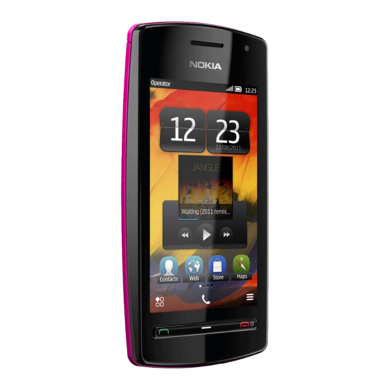
Nokia 600
1
SERVICE MANUAL
RM-701
Conf idential | Copyright © 2011 Nokia | A ll rights reserved
Level 1&2
Transceiver characteristics
Band
WCDMA 850/900/1700/1900/2100
GSM 850/900/1800/1900
Display
3.2" TFT Capacitive touch with 16.7 M colors
640 x 360 pixels
Camera
5 Mpix EDoF camera with LED flash
Operating System
Symbian Belle
Connections:
USB 2.0
3.5mm Jack
Micro USB
Bluetooth
NFC
WLAN
FM RX/TX
GPS
TV Out via IVE3.5
Transceiver with BL-4J battery pack
Talk time
GSM:
Up to 15h
WC DMA:
Up to 6,5h
Note:
Talk times are dependent on network
parameters
and phone settings
Nokia 600
RM-701
Service Manual Level 1&2
Standby
GSM:
Up to 540h
WC DMA:
Up to 600h
Version 1.0
Advertisement
Table of Contents

Related Manuals for Nokia 600


Summary of Contents for Nokia 600
- Page 1 Up to 15h Up to 540h WC DMA: WC DMA: Up to 6,5h Up to 600h Note: Talk times are dependent on network parameters and phone settings Conf idential | Copyright © 2011 Nokia | A ll rights reserved Version 1.0...
-
Page 2: Table Of Contents
BATTERY INFORMATION..............................8 EXPLODED VIEW ................................. 9 SERVICE DEVICES ................................10 SOFTWARE UPDATE................................11 DISASSEMBLY INSTRUCTIONS ............................12 10. ASSEMBLY HINTS................................18 11. SOLDER COMPONENTS ..............................20 Conf idential | Copyright © 2011 Nokia | A ll rights reserved Version 1.0... - Page 3 25.08.2011 First approved version The purpose of this document is to help NOKIA service levels 1 and 2 workshop technicians to carry out service to NOKIA products. This Service Manual is to be used only by authorized NOKIA service suppliers, and the content of it is confidential. Please note that NOKIA provides also other guidance documents (e.g.
-
Page 4: Copyright
Nokia operates a policy of continuous development. Nokia reserves the right to make changes and improvements to any of the products described in this document without prior notice. Under no circumstances shall Nokia be responsible for any loss of data or income or any special, incidental, consequential or indirect damages howsoever caused. -
Page 5: Warnings And Cautions
3. Use only approved components as specified in the parts list. 4. Ensure all components, modules screws and insulators are correctly re–fitted after servicing and alignment. 5. Ensure all cables and wires are repositioned correctly Conf idential | Copyright © 2011 Nokia | A ll rights reserved Version 1.0... -
Page 6: Esd Protection
ESD protected spare part packages MUST NOT be opened/closed out of an ESD Protected Area. For more information and local requirements about ESD protection and ESD Protected Area, contact your local Nokia After Market Services representative. Conf idential | Copyright © 2011 Nokia | A ll rights reserved Version 1.0... -
Page 7: Care And Maintenance
All of the above suggestions apply equally to the product, battery, charger or any accessory. Conf idential | Copyright © 2011 Nokia | A ll rights reserved Version 1.0... -
Page 8: Battery Information
Batteries’ performance is particularly limited in temperatures well below freezing. Do not dispose batteries in a fire! Dispose of batteries according to local regulations (e.g. recycling). Do not dispose as household waste. Conf idential | Copyright © 2011 Nokia | A ll rights reserved Version 1.0... -
Page 9: Exploded View
BATTERY COVER ASSEMBLY (I0027 - I0028) BATTERY COVER I0027 NFC FLEX I0028 Only available Not reuseable Repair/swap Ver. 1.0 as assembly after removal only in level 3 Conf idential | Copyright © 2011 Nokia | A ll rights reserved Version 1.0... -
Page 10: Service Devices
For more information, refer to the Service Bulletin (SB-011) on Nokia Online. Supplier or manufacturer contacts for tool re-order can be found in “Recommended service equipment” document on Nokia Online. Conf idential | Copyright © 2011 Nokia | A ll rights reserved Version 1.0... -
Page 11: Software Update
To use the FLS-5 Flash Dongle, follow the user guide inside the sales package. Please check always for the latest version of flash software, which is available on Nokia Online. Conf idential | Copyright © 2011 Nokia | A ll rights reserved... -
Page 12: Disassembly Instructions
3) Protect the TOUCH WINDOW with protective film. 4) Slide open the BATTERY COVER. 5) Remove the BATTERY COVER. 6) Unscrew the six TORX+ size 6 screws in the order shown. Conf idential | Copyright © 2011 Nokia | A ll rights reserved Version 1.0... - Page 13 Be careful not to damage the connector or any nearby components. 11) Lift up and remove the ENGINE BOARD. 12) Protect the DISPLAY with protective film. Conf idential | Copyright © 2011 Nokia | A ll rights reserved Version 1.0...
- Page 14 17) Remove the CAMERA MODULE with the camera 18) Peel off the DOMESHEET with the tweezers. Do removal tool SS-88. not use it again. Discard it. Conf idential | Copyright © 2011 Nokia | A ll rights reserved Version 1.0...
- Page 15 22) Remove the EARPIECE GASKET with the tweezers. Do not use it again. Discard it. 23) Remove the KEYMAT with the tweezers. 24) Remove the END CAP. Conf idential | Copyright © 2011 Nokia | A ll rights reserved Version 1.0...
- Page 16 Discard it. 29) Use the SS-93 to release the two clips from both 30) Remove the ANTENNA FRAME. sides of the ANTENNA FRAME. Conf idential | Copyright © 2011 Nokia | A ll rights reserved Version 1.0...
- Page 17 33) Remove the SPEAKER GASKET with the dental 34) The Nokia 600 disassembly is now complete. tool. Do not use it again. Discard it. -END OF DISASSEMBLY- Conf idential | Copyright © 2011 Nokia | A ll rights reserved Version 1.0...
-
Page 18: Assembly Hints
WINDOW and push it down slightly until it snaps. the left side. Slightly push the TOUCH WINDOW and Then attach the TOUCH WINDOW connector. the C-COVER together to have the LOCK KEY in place. Conf idential | Copyright © 2011 Nokia | A ll rights reserved Version 1.0... - Page 19 7) Tighten the two TORX+ size 6 screws to the torque 8) Tighten the four TORX+ size 6 screws to the torque of 13 Ncm. of 17 Ncm. Conf idential | Copyright © 2011 Nokia | A ll rights reserved Version 1.0...
-
Page 20: Solder Components
Service Manual Level 1&2 11. SOLDER COMPONENTS V2407 X2072 V2405 V2406 BOTTOM F3301 X6000 X7590 X6500 F3300 X7591 X6501 G2200 S2403 S2404 X6001 K2405 S2402 Ver. 1.0 Conf idential | Copyright © 2011 Nokia | A ll rights reserved Version 1.0...