Table of Contents
Advertisement
Available languages
Available languages
Quick Links
Advertisement
Table of Contents

Related Manuals for Axminster Professional AP406WL


Summary of Contents for Axminster Professional AP406WL
- Page 1 Code 107656 Code 720773 Original Instructions AP406WL Bench Mounted Woodturning Lathe Code 107656 Code 720773 Deutsch Français Ausführung Version Code 502704 Seiten 25-48 Pages 49-72 AT: 30/03/2022 BOOK VERSION: 6...
- Page 2 Exploded Diagrams/Lists 15-16-17-18-19-20-21 Wiring Diagram Notes EU DECLARATION OF CONFORMITY Cert No: KC-1628INV EU Declaration of Conformity Axminster Tool Centre Ltd This machine complies with the following directives: Axminster Devon EX13 5PH UK axminstertools.com 2006/42/EC 2004/108/EC declares that the machinery described:-...
- Page 3 WHAT’S INCLUDED Quantity Item Part Model Number AP406WL 1 No Bench Mounted Woodturning Lathe 1 No Spanner 1 No Push Rod 1 No Spindle Lock Pin 1 No Motor Plate Handle 1 No Instruction Manual OPTIONAL ACCESSORIES Quantity Item Part Code Number 1 No Lathe Extension with Centring Pin...
- Page 4 GENERAL INSTRUCTIONS FOR 230V MACHINES It is good practice to leave the machine unplugged Good Working Practices/Safety until work is about to commence, also make sure The following suggestions will enable you to observe to unplug the machine when it is not in use, or good working practices, keep yourself and fellow unattended.
- Page 5 SPECIFIC SAFETY INSTRUCTIONS FOR WOODTURNING LATHES 1. Do not use ‘split’ work pieces. faceplates etc.,) can be ‘locked’ onto the lathe mandrel, and in the case of chucks have some form 2. Always start at the lowest speed when starting a of security device to prevent them ‘unwinding’...
- Page 6 ASSEMBLY INSTRUCTIONS Please take some time to read the section entitled be cleaned from the lathe, its components and “Illustration and Description” to identify the accessories prior to it being set up. various parts of your machine so that you are familiar Use degreaser to remove the barrier grease.
- Page 7 ASSEMBLY INSTRUCTIONS Figure 04 Figure 07 Figure 05 Figure 08 Figure 06 Figure 09 3. Lift the lathe bed from the pallet onto a work bench, see figs 7 then refit the headstock, tool rest and tailstock as described in steps 1 and 2, see figure 8 Lathe Stand Assembly (Code: 502705) 1).
- Page 8 ASSEMBLY INSTRUCTIONS Figure 13 Remove the headstock, tool rest assembly and tailstock from the lathe bed as before to make it easier to assemble the stands 2. After removing the above lift the lathe bed using a scissor lift, lifting host or seeking help. 3.
- Page 9 ASSEMBLY INSTRUCTIONS Figure 15 Assembly 2 1. Line up the holes in the lathe extension (H) with the threaded holes in lathe stand (F) and secure using the 3/8” Hex bolts and washers (d), see figure Figure 18 Remove the tailstock stop “ROD” and place safely aside Figure 16 Using the 3/8”...
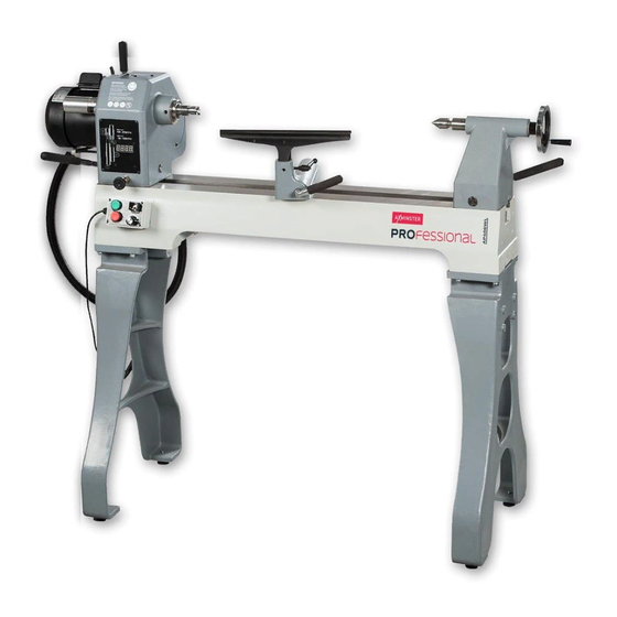
- Page 10 ILLUSTRATION AND DESCRIPTION Motor locking handle Headstock Tailstock Faceplate Live centre Tool rest Banjo lock Tool rest lock Headstock pivot lock Headstock locking handle Control box Spindle speed LED Tailstock wheel Motor plate handle Tailstock barrel lock Access panel Lathe bed Tailstock lock stop Tailstock lock Banjo...
- Page 11 ILLUSTRATION AND DESCRIPTION The control box has a magnetic base enabling it to be ON (Green) and OFF (Red) buttons positioned anywhere on the lathe Forward and Reverse switch The Speed Control Knob, enables you to increase or decrease the speed of the spindle Indexing ring Index lock Headstock Pivot Lock, pull this knob to rotate the headstock to...
- Page 12 OPERATING INSTRUCTIONS Figure 20 Rotating the Headstock The Headstock can be swivelled in any position by lifting up the Headstock locking handle (a) and pulling the Headstock pivot lock (b) out, swivel the Headstock to the desired position is reached, lock in place by pushing down the headstock locking handle (a).
- Page 13 OPERATING INSTRUCTIONS Figure 25 Indexing facility DISCONNECT THE LATHE FROM THE Drive centre MAINS SUPPLY The Indexing ring is situated to the left side of the headstock which incorporates 36 positions at (10˚) segments. To the side of index ring is the index locking pin to lock the spindle in position.
- Page 14 OPERATING INSTRUCTIONS Reposition the belt, making sure the groves in the Figure 27 belt slot into the groves in the pulleys. Pull/push the motor assembly until the belt is under tension, retighten the motor locking handle (a). (See figure Close the pulley access panel and replace the Hex screw.
- Page 15 EXPLODED DIAGRAMS/LISTS Headstock Assembly A...
- Page 16 EXPLODED DIAGRAMS/LISTS Headstock Assembly A...
- Page 17 EXPLODED DIAGRAMS/LISTS Headstock Assembly A...
- Page 18 EXPLODED DIAGRAMS/LISTS Body Assembly B...
- Page 19 EXPLODED DIAGRAMS/LISTS Body Assembly B...
- Page 20 EXPLODED DIAGRAMS/LISTS Stand Assembly C (Optional)
- Page 21 EXPLODED DIAGRAMS/LISTS...
- Page 22 WIRING DIAGRAM...
- Page 23 NOTES...
- Page 24 The packaging is suitable for recycling. Please dispose of it in a responsible manner. EU Countries Only Do not dispose of electric tools together with household waste material. By law they must be collected and recycled separately. Axminster Tools, Axminster Devon EX13 5PH axminstertools.com...
- Page 25 Art.-Nr. 107656 Art.-Nr. 720773 Originalanleitung AP406WL Tischmontierte Drechselbank Art.-Nr. 107656 Art.-Nr. 720773 Art.-Nr. 502704 DATUM: 30/03/2022 BUCHVERSION: 6...
- Page 26 Ändern der Riemengeschwindigkeit 37-38 Wartung Explosionszeichnungen/Teilelisten 39-40-41-42-43-44-45 Schaltplan Notizen EU-KONFORMITÄTSERKLÄRUNG Zert.-Nr: KC-1628INV EU-Konformitätserklärung Axminster Tool Centre Ltd Diese Maschine entspricht den folgenden Richtlinien: Axminster Devon EX13 5PH UK axminstertools.com 2006/42/EG 2004/108/EG erklärt hiermit, dass die nachfolgend EN ISO 12100: 2010 beschriebene Maschine:...
- Page 27 WAS IST INBEGRIFFEN Anzahl Artikel Pos. Modell-Nr. AP406WL Tischmontierte Drechselbank Schraubenschlüssel Ausstoßdorn Spindelarretierstift Motorplattengriff Bedienungsanleitung OPTIONALES ZUBEHÖR Anzahl Artikel Pos. Art.-Nr. Verlängerungsbett mit Zentrierstift 502704 3 /4 3/8” x 1 ” Sechskantschrauben und 8 x 3/8” Unterlegscheiben Werkzeugauflage Verlängerung Drehbankständer 502705 3/8"...
- Page 28 ALLGEMEINE ANWEISUNGEN FÜR 230V MASCHINEN Es ist ratsam, das Gerät bis zum Beginn der Arbeiten vom Gute Arbeitspraktiken/Sicherheit Stromnetz zu trennen. Ziehen Sie auch den Stecker, wenn Die folgenden Hinweise helfen Ihnen, gute Arbeitspraktiken das Gerät nicht benutzt wird oder unbeaufsichtigt ist. Ziehen einzuhalten, sich selbst und Ihre Kollegen zu schützen und Sie zum Ausstecken immer am Steckergehäuse und nicht Ihre Werkzeuge und Geräte in gutem Zustand zu halten.
- Page 29 SPEZIFISCHE SICHERHEITSHINWEISE FÜR DRECHSELBÄNKE 1. Verwenden Sie keine „rissigen“ Werkstücke. 7. Wenn Ihre Drehbank rückwärts laufen kann, müssen Sie sicherstellen, dass das Montagezubehör (Spannfutter, 2. Starten Sie immer mit der niedrigsten Drehzahl, wenn Sie Aufspannscheiben usw.) auf der Spindel „arretiert“ eine neue Aufgabe beginnen.
- Page 30 MONTAGEANLEITUNG Bitte nehmen Sie sich die Zeit, den Abschnitt „Abbildung Verwenden Sie einen Entfetter, um das Schutzfett zu und Teilebeschreibung“ zu lesen, um die verschiedenen entfernen. Achtung: Es hinterlässt Flecken, wenn es Teile Ihrer Maschine zu kennenzulernen, damit Sie Ihre auf Kleidung usw.
- Page 31 MONTAGEANLEITUNG Abbildung 04 Abbildung 07 Abbildung 05 Abbildung 08 Abbildung 06 Abbildung 09 3. Heben Sie das Drehbankbett von der Palette auf eine Werkbank, siehe Abb. 7, und montieren Sie dann den Spindelstock, die Werkzeugauflage und den Reitstock wie in Schritt 1 und 2 beschrieben, siehe Abb.
- Page 32 MONTAGEANLEITUNG Abbildung 13 Entfernen Sie den Spindelstock, die Werkzeugauflage und den Reitstock wie zuvor vom Drehbankbett, um die Montage der Ständer zu erleichtern. 2. Heben Sie das Drehbankbett nach dem Entfernen der oben genannten Teile mit einer Scherenhebebühne, einer Hebevorrichtung oder mit Hilfe an. 3.
- Page 33 MONTAGEANLEITUNG Abbildung 15 Montage 2 1. Richten Sie die Löcher in der Drehbankverlängerung (H) mit den Gewindelöchern im Drehbankständer (F) aus und befestigen Sie sie mit den 3/8” Sechskantschrauben und Unterlegscheiben (D) (siehe Abbildung 18). Abbildung 18 Den Reitstock-Anschlagstab entfernen und sicher ablegen Abbildung 16 Befestigen Sie die Drehbankverlängerung mit den 3/8”...
- Page 34 ABBILDUNG UND BESCHREIBUNG Motorverriegelungsgriff Spindelstock Reitstock Aufspannscheibe Mitlaufkörnerspitze Werkzeugauflage Klemmhebel Arretierung der Handauflagenunterteil Werkzeugauflage Verriegelung des Spindelstocks Spindelstock- Verriegelungsgriff Schaltkasten LED-Anzeige Spindeldrehzahl Reitstockrad Griff der Motorplatte Pinolenarretierung Zugangsklappe Drehbett Reitstockanschlag Reitstockarretierung Handauflagenunterteil...
- Page 35 ABBILDUNG UND BESCHREIBUNG Das Steuergerät ist mit einem Magnetfuß ausgestattet, so dass es an Tasten EIN (grün) und AUS (rot) jeder beliebigen Stelle der Drehbank angebracht werden kann. Vorwärts/Rückwärts-Schalter Mit dem Drehzahlregler können Sie die Geschwindigkeit der Spindel erhöhen oder verringern. Teilungsring Indexsicherungsstift Verriegelung des Spindelstocks: Ziehen Sie diesen Knopf, um den...
- Page 36 BEDIENUNGSANLEITUNG Abbildung 20 Drehen des Spindelstocks Der Spindelstock kann in jede beliebige Position geschwenkt werden, indem Sie den Spindelstock- Feststellgriff (A) anheben und die Spindelstock- Schwenkverriegelung (B) herausziehen, den Spindelstock bis zur gewünschten Position schwenken und durch Herunterdrücken des Spindelstock-Feststellgriffs (A) verriegeln.
- Page 37 BEDIENUNGSANLEITUNG Abbildung 25 Teileinrichtung TRENNEN SIE DIE DREHBANK VOM Stirnmitnehmer STROMNETZ Der Teilungsring befindet sich auf der linken Seite des Spindelstocks und verfügt über 36 Positionen in (10˚) Segmenten. An der Seite des Teilungsrings befindet sich der Sicherungsstift, der die Spindel in ihrer Position arretiert. Die Teileinrichtung ist nützlich für Kannelierungen, Ziffernblätter und die genaue Positionierung von Bohrungen.
- Page 38 BEDIENUNGSANLEITUNG Abbildung 27 Setzen Sie den Riemen wieder auf und achten Sie darauf, dass die Rillen des Riemens in die Rillen der Riemenscheiben greifen. Ziehen/schieben Sie die Motoreinheit, bis der Riemen unter Spannung steht, und ziehen Sie den Motorverriegelungsgriff (A) wieder fest. (Siehe Abbildung 27) Schließen Sie die Zugangsklappe der Riemenscheibe und setzen Sie die Sechskantschraube wieder ein.
- Page 39 EXPLOSIONSZEICHNUNGEN/TEILELISTEN Spindelstock A...
- Page 40 EXPLOSIONSZEICHNUNGEN/TEILELISTEN Spindelstock A...
- Page 41 EXPLOSIONSZEICHNUNGEN/TEILELISTEN Spindelstock A...
- Page 42 EXPLOSIONSZEICHNUNGEN/TEILELISTEN Baugruppe B...
- Page 43 EXPLOSIONSZEICHNUNGEN/TEILELISTEN Baugruppe B...
- Page 44 EXPLOSIONSZEICHNUNGEN/TEILELISTEN Ständerbaugruppe C (optional)
- Page 45 EXPLOSIONSZEICHNUNGEN/TEILELISTEN...
- Page 46 SCHALTPLAN...
- Page 47 NOTIZEN...
- Page 48 Die Axminster-Garantie Kaufen Sie voller Vertrauen bei Axminster! Wir sind von der Qualität unserer Maschinen so überzeugt, dass wir auf alle Teile und Arbeiten eine 3-jährige Garantie aussprechen! Weitere Informationen erhalten Sie unter axminstertools.com/3years Die Verpackung kann recycelt werden. Verpackung bitte auf verantwortliche Weise entsorgen.
- Page 49 Code 107656 Code 720773 Mode d'emploi original AP406WL Tour à bois d’établi Code 107656 Code 720773 Code 502704 À : 30/03/2022 VERSION DU LIVRET : 6...
-
Page 50: Table Of Contents
Vues éclatées/listes 63-64-65-66-67-68-69 Schéma de câblage Notes DÉCLARATION DE CONFORMITÉ EUROPÉENNE N° de certificat : KC-1628INV Déclaration de conformité européenne Axminster Tool Centre Ltd Cette machine respecte les directives suivantes : Axminster Devon EX13 5PH R.-U. axminstertools.com 2006/42/CE 2004/108/CE déclare que la machine décrite :-... -
Page 51: Ce Qui Est Inclu
CE QUI EST INCLU Quantité Article Pièce Référence AP406WL Tour à bois d’établi Clé à écrou Poussoir Goupille d'arrêt de la broche Manette de plaque de moteur Mode d'emploi ACCESSOIRES EN OPTION Quantité Article Pièce Numéro de code Rallonge de tour avec goujon de centrage 502704 Boulons hexagonaux 3/8”... -
Page 52: Instructions Générales Pour Les Machines 230V
INSTRUCTIONS GÉNÉRALES POUR LES MACHINES 230V Une bonne pratique à adopter est de laisser la machine Meilleures techniques / sécurité débranchée jusqu’au début du travail ; veillez donc à Les suggestions suivantes vous permettront d’adopter débrancher la machine lorsqu’elle n’est pas utilisée ou les meilleures techniques, d’assurer votre sécurité... -
Page 53: Consignes De Sécurité Spécifiques Pour Les Tours À Bois
CONSIGNES DE SÉCURITÉ SPÉCIFIQUES POUR LES TOURS À BOIS 1. Ne vous servez pas de pièces « fendues ». 7. Si votre tour peut être inversé, vous devez veiller à ce que les accessoires de montage (mandrins, plateaux, 2. Partez toujours de la vitesse la plus basse en etc.) puissent être « verrouillés »... -
Page 54: Consignes De Montage
CONSIGNES DE MONTAGE Prenez le temps de lire la section intitulée « Illustration Utilisez un dégraissant pour ôter la graisse de protection. et description » afin d’identifier les différentes parties Faites attention, il peut tacher les vêtements, etc. ; portez de votre machine et de vous familiariser avec la une combinaison, ainsi que des gants en caoutchouc et terminologie utilisée pour installer et faire fonctionner une protection oculaire. - Page 55 CONSIGNES DE MONTAGE Figure 04 Figure 07 Figure 05 Figure 08 Figure 06 Figure 09 3. Soulevez le banc de tour de la palette vers un établi (voir figure 7) puis remettez en place la poupée, le porte- outil et la contre-poupée en suivant les étapes 1 et 2 (Voir figure 8).
- Page 56 CONSIGNES DE MONTAGE Figure 13 Retirez la poupée, le bloc du porte-outil et la contre-poupée du banc de tour comme auparavant pour faciliter le montage du piètement 2. Après avoir ôté tout cela, soulevez le banc de tour à l’aide d'une table élévatrice à ciseaux, d'un appareil de levage ou avec l’aide de quelqu'un.
- Page 57 CONSIGNES DE MONTAGE Figure 15 Assemblage 2 1. Alignez les trous de la rallonge de tour (H) aux trous taraudés du piètement (F) et fixez à l’aide des boulons hexagonaux 3/8” et des rondelles (D), voir figure 18. Figure 18 Ôtez la « TIGE » de butée de la contre-poupée et mettez-la de côté Figure 16 À...
-
Page 58: Illustration Et Description
ILLUSTRATION ET DESCRIPTION Vis à poignée Poupée du moteur Contre-poupée Plateau Contre-pointe Porte-outil Blocage du porte-outil Blocage du support de porte-outil Blocage du pivot de la poupée Vis à poignée de la poupée Boîtier de commande LED de la vitesse de la broche Blocage du Volant de Manette de plaque... - Page 59 ILLUSTRATION ET DESCRIPTION MARCHE ARRÊT La base magnétique du boîtier de commande permet de le Boutons de marche (vert) et arrêt (rouge) placer partout sur le tour Interrupteur de marche avant-marche arrière Le bouton de commande de la vitesse vous permet d’accroître ou de diminuer la vitesse de la broche Bague d’indexage Doigt...
-
Page 60: Consignes D'utilisation
CONSIGNES D’UTILISATION Figure 20 Rotation de la poupée La poupée peut pivoter dans toutes les positions en soulevant sa vis à poignée (A) et en tirant sur le blocage du pivot de la poupée (B). Faites ensuite pivoter la poupée dans la position souhaitée puis poussez vers le bas sa vis à... - Page 61 CONSIGNES D’UTILISATION Figure 25 Mécanisme d’indexage DÉBRANCHEZ LE TOUR DE Griffe d’entraînement L’ALIMENTATION SECTEUR La bague d’indexage se trouve à gauche de la poupée qui comporte 36 positions par segments de 10°. Le doigt d’indexage qui maintient la broche en place, figure à côté...
- Page 62 CONSIGNES D’UTILISATION Figure 27 Remettez en place la courroie en veillant à ce que les stries de la courroie s'insèrent dans les gorges des poulies. Tirez/poussez le bloc-moteur jusqu’à ce que la courroie soit tendue, puis resserrez la vis à poignée du moteur (a) (Voir figure 27).
-
Page 63: Vues Éclatées/Listes
VUES ÉCLATÉES/LISTES Ensemble A de la poupée fixe... - Page 64 VUES ÉCLATÉES/LISTES Ensemble A de la poupée fixe...
- Page 65 VUES ÉCLATÉES/LISTES Ensemble A de la poupée fixe...
- Page 66 VUES ÉCLATÉES/LISTES Ensemble B du boîtier d’appareil...
- Page 67 VUES ÉCLATÉES/LISTES Ensemble B du boîtier d’appareil...
- Page 68 VUES ÉCLATÉES/LISTES Ensemble C du piètement (en option)
- Page 69 VUES ÉCLATÉES/LISTES...
-
Page 70: Schéma De Câblage
SCHÉMA DE CÂBLAGE... -
Page 71: Notes
NOTES... -
Page 72: Axminstertools.com
Cet emballage peut être recyclé. Veuillez le jeter de manière responsable. Pays de l’UE uniquement Ne jetez pas les outils électriques avec les déchets ménagers. La loi vous impose un tri et un recyclage distinct. Axminster Tools, Axminster Devon EX13 5PH, R.-U. axminstertools.com...