
Related Manuals for Hisense AS-36HR4SDKVT


Summary of Contents for Hisense AS-36HR4SDKVT
- Page 1 Version: 1.5 Hisense Corporation MODEL: AS-36HR4SDKVT STRONG NEO Premium Classic A...
-
Page 2: Safety Considerations
1. Safety Considerations IMPORTANT! Please Read Before Starting This air conditioning system meets strict safety and operating standards. As the installer or service person, it is an important part of your job to install or service the system, so it operates safely and efficiently. -
Page 3: When Transporting
fire hazard. When Transporting Be careful when picking up and moving the indoor and outdoor units. Get a partner to help, and bend your knees when lifting to reduce strain on your back. Sharp edges or thin aluminum fins on the air conditioner can cut your fingers. -
Page 4: Product Specifications
Product Specifications AS-36HR4SDKVT Model No. Type T1, H/P, ON/OFF Ratings Cooling Capacity 8400 Heating Capacity 8200 Rated Input-Cooling 2215 Rated Input-Heating 2155 Moisture Removal High m3/h 1800 Air Circulation Mid m3/h 1200 Low m3/h EER for Cooling 3.79 COP for Heating 3.81... - Page 5 Power Supply Voltage, Frequency, Phase 220-240V~,50Hz,1P Cooling (A) Rated Current Heating (A) System pressures in cooling rated conditions Max suction pressure Max discharge pressure 4.15 System Compressor Compressor type Rotary Compressor Model No. ATG290V1UMT Compressor MFG GMCC Connecting Pipe Diameter Liquid Pipe inch Gas Pipe...
-
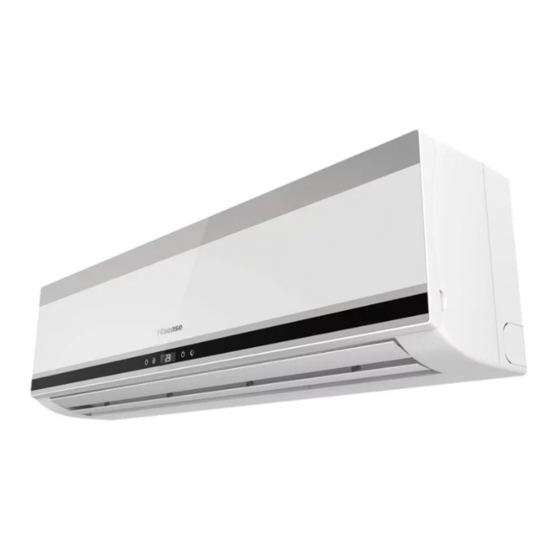
Page 6: Product Picture And Drawing
3. Product Picture and Drawing 3-1. Product Pictures Indoor units: View Remote controller: Model View... - Page 7 3-2. Product dimensions Indoor units: Model W (mm) H (mm) D (mm) AS-36HR4SDKVT 1280...
-
Page 8: Outdoor Units
Outdoor units: Model (mm) (mm) (mm) (mm) (mm) (mm) (mm) AS-36HR4SDKVT 365.5... -
Page 9: Installation Instruction
4. Installation Instruction To prevent abnormal heat generation and the possibility of fire, do not place obstacles, enclosures and grilles in front of or surrounding the air conditioner in a way that may clock air flow. And, more than 1 meter away from any antenna or power lines or connecting wires used for TV, radio, telephone, security system, or intercom. -
Page 10: Outdoor Unit
△ Select a location that will hold the weight of the unit. △ Select a location where tubing and drain hose have the shortest run to the outside. (See a) △ Allow room for operation and maintenance as well as unrestricted air flow around the unit. (See b) △... - Page 11 and decreased service life. △ Install cushion rubber under unit’s feet to reduce vibration and noise. △ Use lug bolts or equal to bolt down unit, reducing vibration and noise. Recommended Wire Diameter:...
- Page 12 4-2. Electric Wiring Diagram Model Indoor unit Size Indoor unit Diagram Outdoor unit Diagram 1280 1837708 1821214 AS-3 HR4SDKVT...
- Page 13 Indoor: 1837708 Outdoor: 1821214...
-
Page 14: Refrigerant Flow System
4-3. Refrigerant Flow System NOTE: In different models, the throttle assembly may be Capillary or Electronic expansion valve. -
Page 15: Air Purging And Leakage Test
4-4. Air Purging and Leakage Test 1. Connect charging hose of manifold valve to charge end of low pressure valve (both high/low pressure valves must be tightly shut). 2. Connect joint of charging hose to vacuum pump. 3. Fully open the handle of Lo manifold valve. 4. -
Page 16: Operation Test
4-5. Test Running △ Check after Installation Items to be checked Possible malfunction Has it been fixed firmly? The unit may drop, shake or emit noise. It may cause insufficient Have you done the refrigerant leakage test? cooling(heating)capacity Is heat insulation sufficient? It may cause condensation and dripping. -
Page 17: Function Operation
5. Function Operation 5-1. Operation Range (cooling and heating) Model : Temperature Indoor Air Intake Temp. Outdoor Air Intake Temp Maximum 43 ℃ COOLING Minimum 16℃ 16℃ Maximum 30℃ 24℃ HEATING Minimum -10℃ Mexico Model : Temperature Indoor Air Intake Temp. Outdoor Air Intake Temp 46 ℃... -
Page 19: Function Instruction
Function Instruction △ 1.Major general technical parameters 1-1 Remote receiver distance(front of the air conditioner): 8 m. 1-2 Remote receiver angle: Less than 60 degrees. 1-3 Temperature control accuracy: ±1℃. 1-4 Time error: Less than 1%.、 2. Functions of the controller 2-1 Display panel I. - Page 20 flash for 5 seconds while displayed. Running LED:It is on during operation. It is flashing when the unit defrost. TIMER LED:When the timer mode works, the LED will be lighted. Sleep LED:When the sleep mode works, the LED will be lighted, and after 10s, the LED will be off. Compressor LED:It lights up when compressor is running.
-
Page 21: Cooling-Run Mode
OFF-Timer setting less than 8 hours, it will keep the Sleep mode till the OFF-Timer setting; if the OFF-Timer setting more than 8 hours, it will cancel the OFF-Timer setting after the Sleep mode OFF. (3)When the Sleep mode is select with Cooling mode, if the room temperature not less than 26℃, the setting temperature will not be adjusted, otherwise, the setting temperature will be raised by 1℃... -
Page 22: Heating-Run Mode
3-6-2 Indoor fan operation (1)When the indoor fan keep in running condition, this operation state could be controlled by the remote control with High, Median, Low and Automatic setting. (2)When the appliance is set Automatic condition in the Cool mode for the first time, the fan speed will run at Low setting. - Page 23 When the appliance run in Heat mode condition, the indoor fan motor operation is shown as following to prevent the cooling air come out during the appliance operation. When the appliance turn in the anti-cold air system in the Extra-LOW (Tapped motor set in LOW, sic passim) during the compressor operation, the louver swang to the Cool air protection position, the louver recovers to the original position after the air volume change to LOW.
- Page 24 position plus 5º . 4-3-8-4 Outdoor fan The outdoor fan speeds except single speed motor can be changed according to outdoor ambient temperatures. 3-7-6 4-way valve State: It is electrified in heating. Switchover: When initially powered on for heating, the 4-way valve is activated immediately. In the change from cooling to heating, it needs an interval of 50 seconds for the 4-way valve to change over from being interrupted to being activated.
-
Page 25: Special Function Fnstruction
≥2 Dehumidifying area II: The compressor stops for 5 minutes and operators for 5 minutes at the lowest frequency. Dehumidifying area III: The compressor stops. 3-10 Fan Only Mode Operation During the appliance run in this mode, the compressor and outdoor fan stop, the indoor fan operate under the pre-setting of air volume, and the louver swing, and the indoor fan speed same as the Heating Mode. -
Page 26: Electrical Characteristics
A:The accumulated time of defrosting is longer than 12 minutes (EEPROM setting value in the current operating mode); B:If the temperature of coiled pipe is equal to or higher than 14 degrees centigrade (EEPROM setting value in the current operating mode); Actions of exiting the defrosting state: The compressor stops, and 50 seconds later the four-way valve opens, and another 10 seconds later the compressor and outdoor fan restart and begin normal operation. - Page 27 IU-PCB-1 IU-PCB-5...
- Page 28 OU-PCB-1...
-
Page 29: Fan Motor
6-2. Fan Motor Drawings attached: INDOOR AC FAN OUTDOOR AC FAN Test in resistance. TOOL: Multimeter. Test the resistance of the main winding. The indoor fan motor is fault if the resistance of main winding 0(short circuit)or∞(open circuit). Test in voltage TOOL: Multimeter. -
Page 30: Temperature Sensor
Indoor DC Fan Motor Outdoor DC Fan Motor 6-3. Temperature Sensor Parameter table attached: THE PARAMETER OF THE INDOOR COIL AND INDOOR ROOM SENSOR (R(0)=15k B(0/100)=3450) Model AS-3 HR4SDKVT... - Page 31 Temperature(℃) Resistance(k) Voltage(V) Temperature(℃) Resistance(k) Voltage(V) 38.757 0.58143512 4.292 2.715076661 36.844 0.60795346 4.137 2.76063657 35.038 0.63530819 3.989 2.805589174 33.331 0.66352684 3.847 2.850117358 31.719 0.69257720 3.711 2.894109636 30.196 0.72246147 3.58 2.937788018 28.755 0.75321223 3.455 2.980713033 27.392 0.78480857 3.335 3.023117961 26.103 0.81722911 3.219 3.065272268 24.882...
- Page 32 5.372 2.43506494 0.986 4.189944134 5.172 2.48247664 0.957 4.210004953 4.981 2.52951096 0.93 4.228855721 4.797 2.57653834 0.904 4.247168554 4.622 2.62291710 0.878 4.265640683 4.453 2.66931854 Note: the AD value in the table is calculated on the basis of the pull-down resistor is 5.1K.
-
Page 33: Troubleshooting
7.Trouble Shooting 7-1. Error Code Table 7.1 The LED of indoor display board will show the error sequence automatically when the unit has the following trouble. Remark: Light o Flash x OFF Error ★ code Content Remark The root cause is may be one of the following It is normally for protection, When the indoor pipe temperature between 53℃<T<63℃, the outdoor fan motor will stop running. - Page 34 High or Low pressure The pressure switch is working protection for outdoor The pressure switch is invalid uint The outdoor control board is invalid The failure for The indoor room temperature sensor loose; temperature sensor of The indoor room temperature sensor is failure; indoor room The indoor control board is failure.