Table of Contents
Advertisement
Quick Links
Owner's Manual
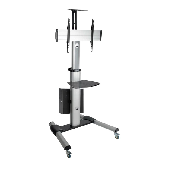
Mobile Flat-Panel
Este manual está disponible en español en la página de Tripp Lite: tripplite.com
Ce manuel est disponible en français sur le site Web de Tripp Lite : tripplite.com
Русскоязычная версия настоящего руководства представлена на веб-сайте компании
Dieses Handbuch ist in deutscher Sprache auf der Tripp Lite-Website verfügbar: tripplite.com
CAUTION: DO NOT EXCEED MAXIMUM LISTED WEIGHT CAPACITY. SERIOUS INJURY OR
PROPERTY DAMAGE MAY OCCUR!
200 x 200 / 300 x 300
400 x 200 / 400 x 400
600 x 400
WARRANTY REGISTRATION
1111 W. 35th Street, Chicago, IL 60609 USA • tripplite.com/support
Copyright © 2021 Tripp Lite. All rights reserved.
Floor Stand
Model: DMCS3270XP
Tripp Lite по адресу: tripplite.com
70"
MAX
Register your product today and be
automatically entered to win an ISOBAR
surge protector in our monthly drawing!
tripplite.com/warranty
1
150 lb.
150 lb.
(68 kg)
(68 kg)
MAX
MAX
®
Advertisement
Table of Contents

Related Manuals for Tripp Lite DMCS3270XPBB


Summary of Contents for Tripp Lite DMCS3270XPBB
- Page 1 Model: DMCS3270XP Este manual está disponible en español en la página de Tripp Lite: tripplite.com Ce manuel est disponible en français sur le site Web de Tripp Lite : tripplite.com Русскоязычная версия настоящего руководства представлена на веб-сайте компании Tripp Lite по адресу: tripplite.com Dieses Handbuch ist in deutscher Sprache auf der Tripp Lite-Website verfügbar: tripplite.com...
-
Page 2: Warranty And Product Registration
FREE Tripp Lite product!* * No purchase necessary. Void where prohibited. Some restrictions apply. See website for details. Tripp Lite has a policy of continuous improvement. Specifications are subject to change without notice. Photos and illustrations may differ slightly from actual products. -
Page 3: Component Checklist
Component Checklist IMPORTANT: Ensure that you have received all parts according to the component checklist prior to installing. If any parts are missing or faulty, visit tripplite.com/support for service. Middle Base Left Leg Right Leg Left Cover Right Cover Support Plate Universal Plate Plastic Cover (x2) Adapter Bracket (x2) -
Page 4: Assembling The Base
1. Assembling the Base Never Overtighten Screws 1) Insert Right Leg C into Middle Base A. Align the holes in the Right Leg to the holes in the Middle Base. Secure with Screws Q and Allen Wrench Y. Repeat this step for Left Leg B. 2) Each caster can be adjusted independently for fine tuning. - Page 5 2. Attaching the Column to the Base Place Plastic Handle K on Column. Attach Column to Middle Base with Screws W. Tighten all screws, then tighten Safety Screw R with user- supplied Phillips-head screwdriver. Attach Left Cover D and Right Cover E to Legs.
- Page 6 3. Installing the Support Plate Attach Support Plate F to Column with Screws U and user-supplied Phillips-head screwdriver. Attach Top Cover L to Support Plate. 4. Installing the Adapter Brackets Insert Washers P into back of Universal Plate G along plate rails. Insert Adapter Brackets I into Universal Plate.
- Page 7 4. Installing the Adapter Brackets Attach Plastic Covers H to both ends of Universal Plate using Screws V. Tighten all screws with user-supplied Phillips- head screwdriver. min. 200 mm - max. 600 mm Adjust Adapter Brackets to fit VESA hole pattern on your display. Tighten all Screws. NOTE: Verify proper alignment of all holes.
- Page 8 4. Installing the Adapter Brackets 4.1 For Flat-Back Screens Note: Choose the appropriate Screws, Washers and Spacers (if needed) according to the type of screen. Screw the Adapter Brackets onto the display. CAUTION: Tighten all screws but do not over tighten. 4.2 For Recessed-Back Screens or Accessing A/V Inputs Note: Choose the appropriate Screws, Washers and Spacers (if needed) according to the type of screen.
- Page 9 5. Hooking the Display to the Support Plate Hook Universal Plate onto Support Plate. Secure by tightening Screws X with user- supplied Phillips-head screwdriver. CAUTION: Be sure the display is correctly mounted and that the screws are safely tightened before releasing the display. 6.
-
Page 10: Cable Management
7. Cable Management 8. Installing the Camera Shelf Attach Camera Shelf N to Connecting Plate M using Screws S & T. Tighten screws with user-supplied Phillips-head screwdriver. -
Page 11: Display Orientation
9. Installing the Connecting Plate Attach Connecting Plate to Column at the desired height using Screws R. Tighten screws with user-supplied Phillips-head screwdriver. 10. Display Orientation Remove the two Retighten the removed screws Install at least two Screws V screws to rotate the into the different hole position diagonally to secure the display. - Page 12 11. Adjustment Tighten the knobs to secure. Loosen the knobs to adjust the display to the desired angle. Display panel center height measured from floor. Maintenance • Check that the bracket is secure and safe to use at regular intervals (at least every three months). •...