Table of Contents
Advertisement
Quick Links
Register your product for quicker service and ultimate peace of mind.
You could also win an ISOBAR6ULTRA surge protector—a $100 value!
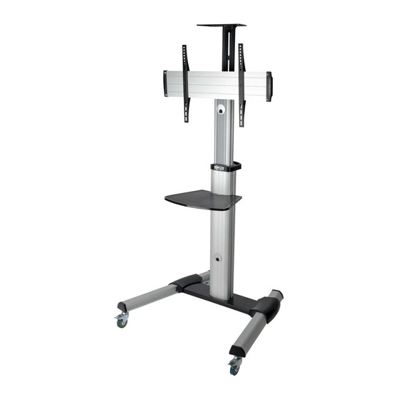
CAUTION: DO NOT EXCEED MAXIMUM LISTED WEIGHT CAPACITY. SERIOUS INJURY OR
PROPERTY DAMAGE MAY OCCUR!
200 x 200 / 300 x 300
400 x 200 / 400 x 400
600 x 400
Este manual esta disponible en español en la página de Tripp Lite: www.tripplite.com
Ce manuel est disponible en français sur le site Web de Tripp Lite : www.tripplite.com
Русскоязычная версия настоящего руководства представлена на веб-сайте компании
Dieses Handbuch ist in deutscher Sprache auf der Tripp Lite-Website verfügbar: www.tripplite.com
1111 W. 35th Street, Chicago, IL 60609 USA • www.tripplite.com/support
18-06-223-9336AF-EN.indd 1
Owner's Manual
Mobile Flat-Panel
Floor Stand
Model: DMCS3270XP
PROTECT YOUR INVESTMENT!
www.tripplite.com/warranty
Tripp Lite по адресу: www.tripplite.com
Copyright © 2018 Tripp Lite. All rights reserved.
70"
MAX
1
150 lb.
(68 kg)
MAX
6/15/2018 2:38:22 PM
Advertisement
Table of Contents

Related Manuals for Tripp Lite DMCS3270XP


Summary of Contents for Tripp Lite DMCS3270XP
- Page 1 Owner’s Manual Mobile Flat-Panel Floor Stand Model: DMCS3270XP PROTECT YOUR INVESTMENT! Register your product for quicker service and ultimate peace of mind. You could also win an ISOBAR6ULTRA surge protector—a $100 value! www.tripplite.com/warranty CAUTION: DO NOT EXCEED MAXIMUM LISTED WEIGHT CAPACITY. SERIOUS INJURY OR...
-
Page 2: Warranty And Product Registration
NOTE: Read the entire instruction manual before you start installation and assembly. WARNING • Do not begin the installation until you have read and understood the instructions and warnings contained in this manual. If you have any questions regarding any of the instructions or warnings, please visit www.tripplite.com/support. -
Page 3: Component Checklist
Component Checklist IMPORTANT: Ensure that you have received all parts according to the component checklist prior to installing. If any parts are missing or faulty, visit www.tripplite.com/support for service. Middle Base Left Leg Right Leg Left Cover Right Cover Support Plate Universal Plate Plastic Cover (x2) Adapter Bracket (x2) -
Page 4: Assembling The Base
1. Assembling the Base 1) Insert Right Leg C into Middle Base A. Align the holes in the Right Leg to the holes in the Middle Base. Secure with Screws Q and Allen Wrench Y. Repeat this step for Left Leg B. 2) Each caster can be adjusted independently for fine tuning. - Page 5 2. Attaching the Column to the Base Place Plastic Handle K on Column. Attach Column to Middle Base with Screws W. Tighten all screws, then tighten Safety Screw R with user- supplied Phillips-head screwdriver. Attach Left Cover D and Right Cover E to Legs. 18-06-223-9336AF-EN.indd 5 6/15/2018 2:38:24 PM...
- Page 6 3. Installing the Support Plate Attach Support Plate F to Column with Screws U and user-supplied Phillips-head screwdriver. Attach Top Cover L to Support Plate. 4. Installing the Adapter Brackets Insert Washers P into back of Universal Plate G along plate rails. Insert Adapter Brackets I into Universal Plate.
- Page 7 4. Installing the Adapter Brackets Attach Plastic Covers H to both ends of Universal Plate using Screws V. Tighten all screws with user-supplied Phillips- head screwdriver. min. 200 mm - max. 600 mm Adjust Adapter Brackets to fit VESA hole pattern on your display. Tighten all Screws. NOTE: Verify proper alignment of all holes.
- Page 8 4. Installing the Adapter Brackets 4.1 For Flat-Back Screens Note: Choose the appropriate Screws, Washers and Spacers (if needed) according to the type of screen. Screw the Adapter Brackets onto the display. CAUTION: Tighten all screws but do not over tighten. 4.2 For Recessed-Back Screens or Accessing A/V Inputs Note: Choose the appropriate Screws, Washers and Spacers (if needed) according to the type of screen.
- Page 9 5. Hooking the Display to the Support Plate Hook Universal Plate onto Support Plate. Secure by tightening Screws X with user- supplied Phillips-head screwdriver. CAUTION: Be sure the display is correctly mounted and that the screws are safely tightened before releasing the display. 6.
-
Page 10: Cable Management
7. Cable Management 8. Installing the Camera Shelf Attach Camera Shelf N to Connecting Plate M using Screws S & T. Tighten screws with user-supplied Phillips-head screwdriver. 18-06-223-9336AF-EN.indd 10 6/15/2018 2:38:31 PM... -
Page 11: Display Orientation
9. Installing the Connecting Plate Attach Connecting Plate to Column at the desired height using Screws R. Tighten screws with user-supplied Phillips-head screwdriver. 10. Display Orientation Remove the two Retighten the removed screws Install at least two Screws V screws to rotate the into the different hole position diagonally to secure the display. - Page 12 11. Adjustment Tighten the knobs to +5°/-12° secure. Loosen the knobs to adjust the display to the desired angle. 1200mm 1250mm 1300mm 1350mm 1400mm 1450mm 1500mm 1550mm 1600mm Display panel center height measured from floor. Maintenance • Check that the bracket is secure and safe to use at regular intervals (at least every three months). •...