Table of Contents
Advertisement
Quick Links
NARDA
Safety
Test
Solutions
S.r.l. Socio Unico
User's Manual
AMS-8061
AREA MONITOR SELECTIVE
SERIAL NUMBER OF THE INSTRUMENT
You can find the serial number
of the receiver unit baseplate and on the side of the Power Pack.
Serial number is in the form: 000XY00000.
The first three digits and the two letters are the Serial Number prefix, the last five digits
are the Serial Number suffix. The prefix is the same for identical instruments, it changes
only when a configuration change is made to the instrument.
The suffix is different for each instrument.
Document AMS8061EN-11114-1.32 – Copyright © NARDA 2021
Sales & Support:
Manufacturing Plant:
Via Rimini, 22
Via Benessea, 29/B
20142 - Milano (MI)
17035 - Cisano sul Neva (SV)
Tel.: +39 02 581881
Tel.: +39 0182 58641
Fax: +39 02 58188273
Fax: +39 0182 586400
on the upper cover of the receiver unit, on the side
Advertisement
Table of Contents

Related Manuals for NARDA 8061


Summary of Contents for NARDA 8061
- Page 1 The first three digits and the two letters are the Serial Number prefix, the last five digits are the Serial Number suffix. The prefix is the same for identical instruments, it changes only when a configuration change is made to the instrument. The suffix is different for each instrument. Document AMS8061EN-11114-1.32 – Copyright © NARDA 2021...
- Page 2 NOTE: ® Names and Logo are registered trademarks of Narda Safety Test Solutions GmbH – Trade names are trademarks of the owners. If the instrument is used in any other way than as described in this User’s Manual, it may become unsafe.
- Page 3 1.3 Standard accessories ……............... 1.4 Optional accessories…………………………………………….... 1.5 Main specifications................1.6 Max acquisition time…………………………………………………….. 1.7 AMS-8061 receiver panel……………………………………………… 2 AMS-8061 Installation and first use with NardaAMConfigurator Page 2.1 Introduction.........…........... 2.2 Initial inspection......…............ . 2.3 Working environment....…............2.4 Return for repairs..………............
- Page 4 3 8061SW-02 - User’s guide and Data Display Page 8061SW-02 User’s guide 3.1 Introduction………….........…..........3.2 Hardware requirements......…..……………………………………. 3.3 Software installation……......…............3.4 Password management……………………………………………………………….. 3.4.1 Entering the TERMINAL password………………………………………………… 3.4.1.1 Changing the TERMINAL password…………………………………………….. 3-10 3.4.2 Entering the SETTING password………………………………......3-11 3.4.2.1 Changing the SETTING password………………………….……………………...
- Page 5 4.4.4.3 Record File (Write)………………………………………..………… ....4-23 4.4.4.4 FLD File (Write)………………………………………..….………… ....4-24 4.4.4.5 Event File (Write)………………………………………..………… ....4-24 4.5 First installation - Setting stations to FTP mode ...…………………...... 4-26 4.5.1 Modem, FTP………………………………………………………………………….. 4-44 4.6 AMB-8061 Firmware updates in FTP mode……………………………....Contents...
- Page 6 5-35 5.7.3 Selective Multiband Structure description ………………………………..…. 5-36 5.7.4 GPS information…………………………………………………………………. 5-40 5.7.5 Band Packet description……………………………………………………….. 5-43 6 Action of the wind into AMS-8061 Page 6.1 Introduction………….………………..………………………....6.2 AMS-8061…………………………………………………………………. 7 Service & Troubleshooting & F.A.Q Page 7.1 Service………………………………………………………………………. 7.2 Troubleshooting …………………………….……………………....
-
Page 7: Table Of Contents
Figure Page AMS-8061 Field Monitoring System……………………. EHA-2B-01 Antenna……..………………………………… AMS-8061 receiver unit panel……………………………. AMS-8061 Receiver unit panel…………………………… AMS-8061 Field Monitoring System ..…………………… DB9 Female front side view………………………………. 2-18 Slot for the SIM card………………………….……………. 2-19 Slot for the Micro SD card………………………………… 2-20 NardaAMConfigurator main window……………………. - Page 8 • To prevent the possible danger of electrocution, do not remove any covers, panels or guards installed on the device, and refer only to NARDA Service Centers if maintenance should be necessary; • To maintain adequate protection from fire hazards, replace fuses only with others of the same type and rating;...
- Page 9 Descrizione STAZIONE DI MONITORAGGIO SELETTIVA Description AREA MONITOR SELECTIVE Modello AMS-8061 Model è conforme ai requisiti essenziali delle seguenti Direttive: conforms with the essential requirements of the following Directives: Bassa Tensione 2014/35/EU Low Voltage Compatibiltà...
- Page 10 This page has been left blank intentionally Safety Considerations...
-
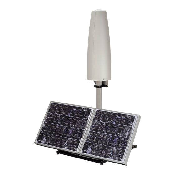
Page 11: Ams-8061 Field Monitoring System
1 – General information This Users Manual contains the following annexes: 1.1 Documentation • A form to be returned to NARDA with the device when requesting service. • A checklist of the accessories included in the shipment. The AMS-8061 system is a revolutionary, accurate and reliable solution for 1.2 Introduction... - Page 12 1.3 Standard accessories Standard accessories included with AMS-8061 unit are: The baseplate includes: • AMS-8061 Area Monitor Selective • Air filter • Radome with 4pcs. Torx screws M5x16mm and 4 pcs. plastic washer Other accessories: • Solar panels • Support base (iron version);...
-
Page 13: Technical Specifications Of Ams-8061
1.5 Main Specifications Tables 1-1 – 1-2 list the specifications of AMS-8061. TABLE 1-1 Technical Specifications of AMS-8061 Frequency range 100 kHz – 6 GHz (in accordance with antenna specifications) User-Programmable frequency bands Up to 20, individual start-stop frequency settings... - Page 14 Approx. 34 kg (with iron support base) Approx. 29 kg (with aluminum support base) Note (1): AMS-8061 are equipped with 4G modem (for station which serial number starts with 141ZY…..); the previous serial number are equipped with 3G modem. Note (2): Accessory supplied separately (on charge)
-
Page 15: Settings/Queries Of The Ams-8061
Reading of battery Reading of internal temperature Spontaneous call Reporting alarms Reporting via SMS of daily maximum The AMS-8061 system can be equipped with electric and magnetic antenna as reported in the following table: TABLE 1-3 Antennas Specifications Model EHA-2B-01... -
Page 16: Eha-2B-01 Antenna
Fig. 1-2 EHA-2B-01 Antenna The EHA-2B-01 triaxial antenna includes a triaxial magnetic field sensor. Computation of electric field, expressed in V/m by the station, is done assuming the measurement is taken in far field condition where the known ratio between magnetic and electric field allows good correlation accuracy. -
Page 17: Ams-8061 Receiver Unit Panel
1.7 AMS-8061 receiver panel Fig. 1-4 AMS-8061 receiver unit panel Legend: 1) GSM antenna 2) SIM card slot 3) GPS antenna 4A) Status LEDs 4B) Controller LEDs 5) RS232 serial interface connector 6) Power switch 7) Power supply connector 8) RF input N connector... - Page 18 This page has been left blank intentionally General Information...
- Page 19 Any part of the instrument – with the sole exception of the air filters (see Service at chapter 7) - can only be replaced by NARDA, therefore, in case of damage to parts and/or malfunctions, contact the NARDA service center.
-
Page 20: Ams-8061 Field Monitoring System
It is suggested to replace air filter at least once a year or more frequently if needed (see Service at chapter 7) 2.6 Installation The AMS-8061 Field Monitor is designed to operate outdoors, in the vicinity of the electromagnetic fields sources that shall be controlled, and under the most severe environmental conditions. - Page 21 1) Install the Support base on the site to be monitored. In the northern (boreal) hemisphere, the AMS-8061 should be installed with the solar cells facing south, in order to take the best advantage of the solar radiation for continuous recharging of the internal batteries.
- Page 22 (GPRS/FTP, Point to Point or both). The antenna used in the AMS-8061 and the receiver input stage contain highly sensitive elements. Never place the unit in an electrical field higher than the maximum allowed level.
- Page 23 3) Remove the bolt from the pole support, place the pole and fasten it to the base using the bolt with nut and washers. Using the supplied pole, whose characteristics have been carefully assessed, is recommended to avoid any alteration of the field to be monitored.
- Page 24 4) Assembly the pair of solar panels as shown below: The Solar panel mounting kit includes: 1) 40W Solar panel (2 pcs); 2) Hexagon head bolt M4x10mm (4 pcs.); 3) Upper L shaped bracket (1 pc.); 4) Tooth washer Ø4mm (4 pcs.); 5) M4 nut (4 pcs.);...
- Page 25 40W Solar panels Position and align the two solar panels as indicated by the arrow sticker positioned on the side of each panel. Upper L shaped bracket Assembly the Upper L shaped bracket to the upper side of the panel indicated with “UP” label. Installation and use...
- Page 26 S shaped bracket and PA6 black bracket 55deg lower support Assembly the 55deg lower support to the lower side of the panels indicated with “DOWN” label Installation and use...
- Page 27 The solar panel is ready to be mounted on the support base. 6) Unscrew the Pan head screw inside the PA6 black bracket without losing it completely. Installation and use...
- Page 28 7) Insert and slide the Solar panel into the fiberglass pole and position the 55deg lower support on the base 8) Position the Solar panel and the Support base on the ground as shown and install the 55deg lower support. 2-10 Installation and use...
- Page 29 9) Install the 55deg lower support to the support base with the 2 pcs. Pan head machine screw X shaped M4x16mm (16), 2 pcs. Tooth washer Ø4mm (20) and 2 pcs M4 nut (22) remaining. 10) Position the Solar panel and the Support base on the ground as shown below.
- Page 30 11) Fasten the Solar panel by tightening the bracket screws 12) Remove the Power Pack cover. 2-12 Installation and use...
- Page 31 13) Remove the nut from the chock of the solar panel cable. 14) Thread the cable through the hole in the box and screw the nut to fasten the chock to the Power Pack. 15) Place the fuse. Installation and use 2-13...
- Page 32 16) Plug the solar panel connector. 17) Close the Power Pack box. 18) Before mounting the receiver unit on the pole, unscrew the Pan head screw inside the both PA6 black brackets without losing it completely. 2-14 Installation and use...
- Page 33 19) Mount the receiver unit on the pole. 20) Fasten the unit by tightening the bracket screws 21) Remove the nut from the chock of the power cable. Installation and use 2-15...
- Page 34 22) Install the power cable by mounting the chock in the hole of the receiver baseplate; plug the power supply connector to the receiver unit holding by the plastic part. 2-16 Installation and use...
- Page 35 Do not insert or remove the antenna holding it by the head or by the data cable as serious damage may occur. The AMS-8061 station cannot operate without antenna even when downloading acquired field data. In case the antenna is accidentally removed when station is ON a reset will be required: switch the station OFF, connect the triaxial antenna and switch ON again.
-
Page 36: Db9 Female Front Side View
24) In the first connection you must connect the USB port of the AMS-8061 to the PC (USB port) by USB(A)/USB(B) cable and configure the station with NardaAMConfigurator software. It must be make in this way even if the subsequent operations will be done via Ethernet or RS232 or 4G modem. -
Page 37: Slot For The Sim Card
25) AMS-8061 is equipped with a 4G GSM modem (inside the main unit) 2.7 GSM Modem and and antenna that allows remote communication for programming and for SIM Card the remote collection of the data recorded. The GSM modem requires a... -
Page 38: Slot For The Micro Sd Card
§5.8 chapter”. The AMS 8061, as soon as it detects the presence of an Micro SD Card, tries to open the file "SD8061.SD1" and, if successful, tries writing the last <size_of_file>... - Page 39 27) Switch the unit on using the level switch of the AMS-8061 Area Monitor 2.9 Switch the System. AMS-8061 on 28) Once switched the unit on, check the Led ON, Led ETHERNET, Led 2.10 Check the LEDs MICRO SD Card and Led MODEM status as follows:...
-
Page 40: Led Ethernet Status
This Led let the user know about the Ethernet status as shown in the Led ETHERNET status following table. TABLE 2-1 Led Ethernet status Status Action Steady GREEN Ethernet cable is connected The Led let the user know about the state of process as shown in the Led MICRO SD status following table. - Page 41 29) A complete battery charging should be completed (48 hours) before 2.11 Power supply/ starting first connection and/or measurements. battery charging (standard accessory) Execute the same procedure when the battery charger need to function as power supply during measurements. Remove the Power Pack cover. Disconnect the solar panel from the Power Pack removing the chock.
- Page 42 Plug the battery charger with the proper adapter to the mains outlet before connect the multipole connector to the Power pack. Fasten the cable to the strain relief. Thread the cable through the hole in the box and screw the nut to fasten the chock to the Power Pack.
- Page 43 Any part of the instrument, including the battery, can only be replaced by NARDA, therefore in case of any damages to parts and/or malfunctions, please contact the NARDA Service Center. The selective unit is OFF every time the battery voltage is lower than 11 V.
- Page 44 31) The external power supply optional accessory allows to connect the 2.13 External power AMS-8061 directly to the mains power without needing solar panel and supply battery pack connection (optional accessory) Plug the multipole battery charger connector to the male panel connector of the external power supply.
- Page 45 Plug the battery charger with the proper adapter to the mains outlet before connect the multipole connector to the Power pack. Remove the nut from the chock of the external power supply. Installation and use 2-27...
- Page 46 Install the power cable by mounting the chock in the hole of the receiver baseplate; plug the external power supply connector to the receiver unit holding by the plastic part. 2-28 Installation and use...
-
Page 47: Nardaamconfigurator Main Window
Fig. 2-5 NardaAMConfigurator main window Follow the instructions step-by-step. The configuration wizard help you to configure AMS-8061 station: • Auto-detect the connection of the station to the PC by RS232 or USB • Check the status of battery and the version of the FW •... - Page 48 A micro switch on the side of the main unit is tripped when the radome is opened. It is possible to activate an alarm, sent by AMS-8061 to any GSM mobile phone, warning of any attempts to tamper with the device.
- Page 49 Tighten the four screws to fix the Radome. 34) The AMS-8061 is usually installed outdoors where atmospheric agents, 2.16 Bags especially strong winds, can endanger its stability. To ensure the necessary stability under the worst possible conditions, the unit is supplied with three ballast bags that can be filled with water or sand and fastened to the base of the mast.
- Page 50 This page has been left blank intentionally 2-32 Installation and use...
- Page 51 - USB or RS232 or Ethernet cable connection - Line or GSM PC modem (AMS-8061 set for Point-to-Point data communication) - Internet by means of the user’s FTP server (AMS-8061 set for FTP data communication) The software is based on the Windows™ operating system.
- Page 52 3.2 Hardware To ensure the proper operations of the 8061SW-02 software, the minimum hardware requirements of the Personal Computer are: Requirements • Pentium processor or equivalent; • at least 256 Mb RAM; • at least 100 Mb of free space on your hard disk; •...
- Page 53 3.3 Software To install the 8061SW-02 on PC from the supplied Software Media proceed as follows: installation In Computer Resources, browse the Software Media. To start the installation double click on the 8061NSTS Setup icon. The User must have administrator privileges to install the 8061SW-02 software in Windows 7, 8 etc.;...
- Page 54 Follow set-up program instructions. The installation can be aborted by clicking on Cancel. The installation folder must be specified. Click Next to confirm the default folder (recommended) or Change to modify. Click OK to confirm the directory. You can also type a different name; in Windows 7 the maximum number of characters for the name is 24 (including spaces);...
- Page 55 Click Next to proceed installing. In case of existing installation, the software will ask the user if he wants to cancel all the Passwords. If the answer is YES, the following message will appear: If select YES, all the stations and measurements already saved will be hidden, but still accessible by adding all the stations used and maintaining the original name (respecting upper and lower case letters) and phone number.
- Page 56 The installing status is displayed then: Click Finish to complete and exit the installer. The folder 8061NSTS is created under Programs with the icon 8061SW-02 on desktop. 8061SW-02 - User’s guide and Data Display...
- Page 57 Windows 7 or later also allows to mark the application so that it always be used with administrator rights. After the installation, select with right mouse button the 8061 NSTS icon on desktop, choose the voice “Properties” (should be the last one of the menu).
- Page 58 3.4 Password 8061SW-02 allows the user to create a list of all stations that are going to be used. The list include parameters, like telephone number, station name, management ecc. needed by the software to access every single station. To avoid any improper modification of parameters included in the station list by non 3.4.1 Entering admitted personnel a Terminal password is needed.
- Page 59 If the answer is YES, the screen looks like this: The User can enter any sequence of alphanumerical characters; any special characters are not allowed. We recommend to take note of the Terminal PASSWORD entered. After entering the Password with OK, the software will request confirmation of the password before registering it into the system.
- Page 60 3.4.1.1 Changing the If it is necessary to change the Terminal Password, just press function TERMINAL password key F10 while the software is displaying the main window that includes the station list. The software displays the message: If the answer is YES, first enter the old Terminal Password, then enter the new one.
- Page 61 PASSWORD which is needed to edit the station settings like storing Rate, station clock, thresholds for alarm, device password saved on the AMS- 8061, etc. The Setting Password screen looks like this: If the answer is YES, the User will be asked to enter and confirm a new Password (which may be different from the Terminal Password).
- Page 62 Every time you have to modify a field, the Setting Password will be requested by the software. At the beginning, for the first setting operations, it would be helpful to leave these password blank, simply pressing enter on the keyboard. Set a password only after all your area monitors will be correctly set, and just in case you need to have an higher security level.
- Page 63 Remote communication in Point-to-point mode is protected by a Device DEVICE password Password that is stored in every AMS-8061 Area Monitor; all the monitoring stations are initialized in the factory with the password “PASSPMM” that is advisable to replace during the first connection following these steps: In Point-to-point communication mode, enter “PASSPMM”...
- Page 64 • Hang up to end the call/connection in progress; • Add Station to add a new AMS-8061 Area Monitor to the list; • Open Log File displays all settings and main activities automatically and manually downloaded from the station •...
- Page 65 The list of remote stations contains the following information: • Station Identifier (Name): the name of the monitoring station; • Telephone Number: the phone number of the station SIM card; • Last Link: date of the latest connection made; • Links: number of completed connections/number of trials;...
- Page 66 3.6 Station management To make a call or download data from an existing Field Monitor, it is necessary to use the Add Station command and add the station to the list. The screen looks like this: 3.6.1 Entering a new station The procedure to add a station is as follows: •...
- Page 67 If a wrong Device Password is entered, the following message appears when trying to access the remote station in Point to Point mode: Entering the Device Password prevents the station from being queried by any unauthorized person who might in some way to know its telephone number.
- Page 68 3.6.2 Removing a To remove a station from the list, click Remove Station. The message is: station If the answer is YES, the software will require to enter the Terminal Password, and the station will be deleted; if the answer is NO, the operation will be aborted.
- Page 69 3.6.4 Automatic data The window for editing or adding the stations also provides an Automatic downloads Download function which makes monitoring fully automatic, with transfer of the data from the station, generation of the .TXT file, etc.. Therefore some stations can be programmed for manual connection and others, after being called, will automatically transfer the data, while others again will automatically call (or be called by) the control PC at a certain time of day and download their data by themselves.
- Page 70 3.6.5 Answering By enabling the command PC Answering, at the scheduled time, the station enabled for Point-to-point communication calls the modem connected to the PC and automatically downloads all its data. To program the station to do that, proceed as follows: •...
- Page 71 3.6.6 Calling When the PC Calling function is enabled, every time the station is called using the CALL or “Scheduled CALL” commands, the data present on the station - and recorded since the latest download - will be automatically downloaded to the PC. This can be very useful because it makes unnecessary to remember the time of the latest download.
- Page 72 The AMS-8061 Area Monitor System can save a certain number of events 3.6.8 Autoload Events in the permanent memory of the station, so as to ensure traceability (independent from the operations of the control center) with regard to the settings and main activities of the station. These events can be downloaded from the station, displayed in text format and copied into the mass memory of the control center to keep updated the station history.
- Page 73 3.7.2 Exporting data The Data Export function creates text files and, if enabled, .bmp files related to the time range specified by the user: After selecting the desired time range (From date – To date) click the Export button to create, in the AUTOFILE directory, the following text files: •...
- Page 74 3.8 Direct readings When the station is connected to the controller PC through the RS232 or USB cable, the Direct Readings button is used to open a window where it is possible to immediately read the basic station data. With this function the User can read the field values acquired by the station without post-processing them;...
- Page 75 3.9 Post settings The Post Settings key is used to open a window where settings can be defined for the selected station. This presetting operation allows to change the settings even if the station cannot be contacted at the specific moment, for any reason. All the settings are saved temporarily and sent to the station during the first link.
- Page 76 The calendar, created automatically by the 8061SW-02 software, always 3.10 Calendar of shows the current month and year and is used to select and display in measurements graphical form the data downloaded from the Field Monitoring station, simply by clicking the button of the desired day or week. Only the buttons with blue characters contain data, which has been previously downloaded from the station.
- Page 77 3.11 Control window Once a link has been successfully established, in Point-to-point mode, the control window is opened for the selected station and it is possible to: • Check the settings and parameters of the station; • Edit the settings (function protected by the Setting Password); •...
- Page 78 The control window is divided in different zones grouping the available 3.12 Description of commands by type and function. The main zones are: controls ALARMS divided in: • Last Field • WARNING • ALARM • Averaging Period • NOTIFY ALARMs through •...
- Page 79 Schedule for SMS divided into: • Telephone number • Time (HH:mm) • Stand by (Q) indicated in number of quarters of an hour; this value affects battery duration • Every (H) • Send REPORT Up to ten mobile phones can be programmed. Both phones will receive the daily report.
- Page 80 • GPS to show the position data; The AMS-8061 has a built-in GPS which allows tracking its position. Data is reported in a NMEA RMC sentence according to NMEA 0183 ver 3.01. As for example, the Latitude in the picture corresponds to 44°...
- Page 81 3.12.1 ALARM Stations are able to notify alarm condition by sending SMS and/or starting a CSD call to the controller PC. Measurement results downloaded from any station include therefore information of any alarm occurred during the monitoring activity. Depending on the local laws, the place of installation, the climatic conditions, the availability of sunlight and the duration of measurement, certain alarms should be enabled for the control and proper operation of the field monitor.
- Page 82 Displays the field averaged in the latest minutes as set in the Averaging Period field. This field is refreshed each time you click the Last field button. AMS-8061 can be remotely queried for this value at any time from a mobile phone by sending the following SMS message to the station:...
- Page 83 3.12.1.3 Averaging This command defines the time period on which the average of the Period field levels will be calculated. The average can be arithmetic (AVG) or quadratic (RMS). In this example, with Send REPORT enabled on Schedule for SMS section, all the mobile phones in the list (max 10), will receive, every day, the maximum value averaged on a period of 6 minutes.
- Page 84 The type of antenna used by a specific station can be read by any mobile phone by sending the SMS message: #SM?IDNpassword*#SM?PRB*. The RF components of the AMS-8061 are tested and calibrated individually. For best overall instrument accuracy the antenna factor is measured on the assembled AMS 8061, thus including all corrections of RF parts, if any.
- Page 85 3.12.1.7 Temperature Temperature alarm. The station features a thermometer for the measurement of the internal limit temperature, in order to have constant control upon the environmental conditions affecting the correct operation of the system. The setting is made as for the other alarms. An alarm is generated in case the internal temperature is >...
- Page 86 3.12.2 Schedule for Programming the station for modem links. MODEM To query the monitoring station by a remote PC linked to a telephone or to a GSM modem, the proper Station modem must be on. In addition, when an alarm occurs, the station can automatically call in CSD mode the telephone number of the modem used by the controller PC.
- Page 87 3.12.3 Schedule for SMS Querying the station with SMS messages Similarly to the “Schedule for MODEM” frame, the “Schedule for SMS” offers the opportunity to define an additional time period during which the station modem will be ON (stand-by mode) and therefore able to receive calls and SMS query and setting commands.
- Page 88 3.12.4 Rate Settings Configuration of data memorization. Data are saved in the station at a frequency (Rate) ranging from 1 to 15 minutes. The Storing Setting affects the battery duration and memory, before old data are overwritten. P.Time: Processing time. It mainly depends on the Bands setting. The minimum Rate should be, at least, =10 x Processing time.
- Page 89 (see chapter 7): Results acquired with the new setting will be displayed starting from the next day. If it is really necessary to change the settings, NARDA recommends one of the following procedure: • Change the station name before making the settings change.
- Page 90 3.12.5 Get DATA Downloading data from the monitoring station to the PC. The data in the internal memory of the station can be downloaded after defining a Start and Stop event as follows: The Start and Stop of the data download is done between the following commands, in any combination.
- Page 91 When the internal clock of the station is changed, some readings may no longer appear contiguous and gaps may be found. For this reason NARDA recommend to use of this function sparingly 8061SW-02 - User’s guide and Data Display 3-41...
- Page 92 3.12.7 Firmware update Update of internal Firmware It is important to update the station firmware in order to use all the new functions added and eliminate any bugs in the software. To update the firmware, use the Execute command. The monitoring station will place the old firmware in its memory and will try to load a new one.
- Page 93 • 3.12.8 GSM Off on Exit The option GSM OFF on Exit sends to the field monitor the request to switch off the station modem in advance, in addition to the request to end the connection. When this option is enabled, at the end of the link (not made after a line break and not after the maximum time without dialogue) the station switches its internal modem off after a time ranging from 1 to 2 minutes, regardless of the residual time set, in...
- Page 94 3.13.4 Sub Bands The Sub Bands window allows viewing and setting up to 20 frequency bands to be investigated. When the tab is opened, the actual bands configuration is shown. Each band can be activated for the selective analysis by ticking the corresponding box.
- Page 95 Very high fields, which frequency is out of the overall frequency range of the created table (from minimum frequency of first band to the maximum frequency of the last one) but within the receiver range (100 kHz – 6 GHz) may cause saturation of the receiver causing wrong measurements.
- Page 96 AMS-8061 sets automatically the larger RBW filter, which allows at least 4 measurements during the scan of the narrowest band of the table. The narrowest band of this table is 1.9 MHz wide (set1: from 0.100 MHz to...
- Page 97 3.14 FTP Main window Once set the station, run the 8061SW-02. After entering the Passwords, the program displays the main window. Select the FTP tab: If the function “Do not move file” is enabled the data stored by the station in the ftp server will be still available for a future download, even from a different PC.
- Page 98 3.15 Data section The first section Data will show which data will be downloaded by the station at the next connection. The default setting is “Since” date-time (your PC clock) – “Up to” now (when the station will access the server). Meanwhile it will be shown the DRIVER INET FTP window;...
- Page 99 3.16 Alarm section The second section, named Alarm, allows the user to set which alarm should be notified, if through FTP connection or SMS to the user mobile phone. The same windows allows the user to set which average type should be performed on the acquired data, AVG or RMS, and the averaging period over which the average calculation is performed.
- Page 100 3.17 Communication The third section, named Communication, allows to change the Schedule section for FTP and Schedule for SMS settings accordingly to your work The first frame Schedule for FTP is in the following way: - in the part Time, you have to decide when the modem has to be switched ON and send data to the FTP server - in the part Stand By, you have to decide for how many quarters of hours, starting from the hours of switching ON, the modem has to stay in stand by...
- Page 101 The frame, Schedule for SMS, allows the user to set in the same way a second time period for the modem to be ON. This is not for FTP connections but it is provided to manage a stand-by period for SMS information exchange The frame Schedule for SMS works in the following way: - in the part Time, you have to decide when the modem has to be switched...
- Page 102 3.18 Sub Bands section The last section, named Sub Bands, shows the frequency range setting for measurement in a table form. For further information see §3.13.4 3-52 8061SW-02 - User’s guide and Data Display...
- Page 103 3.19 Software update To update the software double click on the 8061NSTS Setup. Press Next and follow the installation steps on §3.3 Software installation During the installation process the software will ask the User if he wants to cancel all the existing Passwords. If the answer is YES, all the stations and measurements already saved will be hidden, but still accessible by adding all the stations used and maintaining the original name (respecting upper and lower case letters) and...
- Page 104 3.20 Uninstalling It is possible to remove the 8061SW-02 software from the PC according to the following procedure: Software Run the Uninstall 8061NSTS utility. Press Next to proceed. The software is now removed from the system; click Finish to close uninstaller utility 3-54 8061SW-02 - User’s guide and Data Display...
- Page 105 NUOVACENTRALINACISAN. For station name use only alphanumerical ASCII characters. The new folder is created to collect the data every time the AMS-8061 3.22 Calendar station is queried, dividing them by day, month and year. The data are then...
- Page 106 3.23 Data window By selecting a day or a week shown in blue, the User can access the main menu for graphic representation. Using this menu it is also possible • Display any graphs belonging to any stations (using Open Files); •...
- Page 107 The data window presents the data for the selected day or week in a graphical form. In the example below, it is possible to notice the narrow cyan vertical bands (the color can be set by the User), indicating that the internal GSM modem was transmitting either on the provider request (periodical querying of the phone number), or by the User request, calling the station to make any queries.
- Page 108 3.24 Main Commands The main commands of the 8061SW-02 are: 3.24.1 File This command is used to open any files of any stations or to save the files downloaded. For a detailed description of its use see the paragraphs relative to the specific icons Save and Open here below Some functions of the File command are not enabled when the Zoom function is ON...
- Page 109 3.24.3 Trace The Trace command allows to select which traces will be displayed in the graph. The possible choices are: • Temperature; indicates the temperature of the environment for each data reading; • Battery; provides the voltage of the batteries whenever the field data are stored;...
- Page 110 3.24.4 Marker When the field monitor has been set up to display all data, the graph contains many traces. To ensure accurate measurement of each trace it is possible to enable a marker that will show the value of the electrical or magnetic field, or temperature, or batteries, etc depending on the trace for which it is selected.
- Page 111 3.24.5 Vertical This function is used to select the vertical scale with a linear or logarithmic view and also serves to define the scale range. The screen looks like this: Selecting x 100 Range the maximum sensitivity is displayed. The function Lock (-20/100 lin) is activated when the User want to display on the graph both the temperature and the field trace.
- Page 112 3.25 Secondary Description of command bar: Commands 3.25.1 Save Files Used to save files of measurements in the following formats: 1. Draft (Diagram) (*.RS9) (Default) Archive for future processing of readings; 2. Panel (*.P87) A file with the extension *.P87 is saved, containing the current settings selected with the Setup key, so that the operator can readily restore the preferred settings at a later date.
- Page 113 3.25.1.1 Save File in Files in ASCII format with the .TXT extension contain an (asterisk) ASCII format marking any data, and averaged value, affected by the internal modem and others disturbance activity. The structure of data tables saved in the default .TXT format is as follows: All traces enabled;...
- Page 114 3.25.2 Open Files Used to download and view measurement files previously saved (*.RS9). Also serves to load files of settings (*.P87). If the software is already in graph mode, clicking on Open Files will display all the stations available and also the directory AUTOFILE, containing only the .TXT files created automatically with the AUTO ASCII FILE function.
- Page 115 Selecting the desired year, the menu will display all the months and weeks available: Selecting the month, the software will display the list of all the days containing data. Selecting the desired day and clicking OK the data will be displayed; pressing Cancel to interrupt the operation 8061SW-02 - User’s guide and Data Display 3-65...
- Page 116 Windows Office programs, and cannot be opened using 8061SW-02 software. The latter can be viewed because they are saved in the proprietary graph form of AMS-8061 (.RS9). The time window between Start and Stop is defined by the conditions used during download.
- Page 117 Therefore, with the function Auto ASCII File it is possible to create any graphs with a start and end period of measurement defined in any desired way. For example, from Friday to Monday, or between two months, etc. Of course, this time period must be selected in the download data procedure.
- Page 118 3.25.3 Show Table File This is used to automatically display a table report containing the data relative to the set of traces saved with the Save Export File Setup function. When the Show Table File function is enabled, every other function is disabled.
- Page 119 3.25.5 Zoom Mode This is used for horizontal expansion of the actual measurement displayed (ZOOM) to observe the measurement with better definition. When the ZOOM function is on, the Marker function is enabled as well. A small blue triangle appears on the display and can be moved with the mouse to any point on the graph.
- Page 120 3.25.7 Redraw Used to refresh the screen and redraw the diagram. This operation is necessary in particular when the PC does not have much memory and/or many applications are running at the same time. 3.25.8 Appearance Button and label style can be selected from a Style list Start and End Color button allow selection from a color palette Sample Button and Sample Label show the appearance preview Default button to set appearance to the default parameters...
- Page 121 3.25.9 Setup The use of the Setup key allows to access the window for setting the colors of the graph. It is possible to change the current settings at any time, and the new settings can be saved in a file and restored later. The Setup window looks like this: For each trace of the graph listed under Colors, the desired color can be selected, and these colors can be different for the Screen and for the BMP...
- Page 122 3.25.10 Limit The Limit field is used to set and enable a reference trace on the current screen. The small graph on the upper right of the display gives a preview of the 3.25.10.1 SCREEN results in save or print obtained with the colors selected. Sample Click Exit to close the Setup window without saving the new setting, to maintain the current settings for the graphs displayed after...
- Page 123 3.27 Status window The bottom section of the data window in the 8061SW-02 program displays the status window. This window provides useful information about the program functions and also gives extended and immediate help with the meaning of the commands and options on which the mouse is positioned. A few examples are shown below: Actual operating mode Values relative to Marker position...
- Page 124 This page has been left blank intentionally 3-74 8061SW-02 - User’s guide and Data Display...
-
Page 125: Ftp Communication Mode
AMS-8061 Area Monitor. Both can be automatically set by using the NardaAMConfigurator (see §2.14). The AMS-8061 Area Monitor has been developed to be mainly used in FTP mode with the use of a SIM card. Is it possible to use it also in other modalities like Point to Point but with some limitations. -
Page 126: Point To Point Communication Modes
Point to Point is a direct connection between the area monitor and the computer using the RS232/USB cable or the Modem. The Point to Point with Modem connection, you need a PC modem, a SIM card in the area monitor modem and another SIM car for the PC modem but only if it is GSM. - Page 127 4G modem. AMS-8061 is equipped with an USB port which can be connected to the PC through the supplied USB cable. In Windows 10: When connecting an AMS-8061 to the PC USB port for the first time, a message informing that new hardware “Dispositivo seriale...
- Page 128 When the Change button is clicked, the communication port selector appears. A specific port must be selected to drive the control software to the AMS-8061 Area Monitor: Point to Point and FTP Communication...
- Page 129 Run 8061SW-02 and the main window appears as follows. The software ask you to enter a Terminal and Setting password (see §3.4.1, §3.4.1.1, §3.4.2, §3.4.2.1). Double click the first station listed in the FTP station list (new software installations show the “New8061FTP” station, on the list, as an example).
- Page 130 FTP: These parameters depending on the FTP server you are using. As default, every Narda area monitor is set to work in FTP mode and the parameters you can find in this section are of our FTP server that can be used for preliminary test.
-
Page 131: Usb/Rs232, Point To Point
Click twice on the 8061SW-02 icon to start the software. First a window appears displaying the software release and the port COM assigned. These are the basic operations to follow to work with the AMS-8061. All additional information and explanations can be found on chapter 3 When the Change button is clicked, the communication port selector appears. -
Page 132: Direct Readings" Button
Click the “Exit” button to go back to the main window and select the Point to Point section and use the function direct readings to immediately receive data from the area monitor. For further explanation consult §3.8 Fig. 4-4 “Direct readings” button Direct USB/RS232 communication can also be used for downloading of measurement results where the remote communication is not desired, for example, the GSM signal is very weak or there is no coverage of the... -
Page 133: Modem, Point To Point
Fig. 4-6 Modem, Point to Point To work in this way the area monitor has to be set in this way: These are the basic operations to follow to work with the AMS-8061. All additional information and explanations can be found on chapter 3 Fig. - Page 134 - Insert the Station Identifier: it is the name you decide to give to your monitor station. As default it is the serial number of the station. - Insert the Telephone Number: it is the phone number associated to the SIM card in the area monitor - Insert the Device Password: as default it is PASSPMM For every field the computer will request the Terminal Password (see...
- Page 135 The main window of the software show you all possible information about the area monitor and the antenna. Now passages to do are: - Push the button Enable Settings - Push the button Set Clock - Push the button Sub Bands - Decide how many time and for how long the modem has to be switched on in the frame Schedule MODEM For every field the computer will request the Setting Password (see...
- Page 136 The station clock is very important as every field data stored by the station is Setting station RTC related to time taking, as a reference, the station RTC. (Real Time Clock) Being connected through the cable, the station clock can be set with a good accuracy (the PC clock is used).
- Page 137 Setting Sub Bands Push the Sub Bands button. It shows the frequency range setting for measurement in a table form. Please refer to paragraph 3.13.4 of this manual for further information of using Sub Bands function Point to Point and FTP Communication 4-13...
- Page 138 AMS-8061 is equipped with a 4G GSM modem, which power consumption, How to switch the GSM especially while transmitting, is very high, if compared with the station modem on overall consumption. Additionally, modem transmissions, including communications between terminal (modem) and network that are not under the user control, generate E.M.
- Page 139 Programmed mode The internal modem will remain on and in Stand-by for 60 minutes after the monitor station was switched on. Afterwards, the modem will be switched on and off depending on the “Schedule for MODEM” settings: For further information see paragraph 3.12.2 The above picture shows the “schedule for MODEM”...
- Page 140 Once set the GSM modem you can disconnect the station from the computer and put it in the place choose for monitoring. Connect the modem to the computer to start working in “Modem, Point to Point” mode with the area monitor. Remember that the modem needs to work with a baud-rate of 115200.
- Page 141 In case the software does not detect any modem the message MODEM NOT FELT will be displayed. If the software 8061SW-02 does not detect any modem or you are not sure about the connection with the PC or its working conditions, proceed as follows: To use the “Modem, Point to Point”...
- Page 142 This page has been left blank intentionally 4-18 Point to Point and FTP Communication...
- Page 143 First connection – FTP communication 4.3 General information AMS-8061 area monitor can be set to operate using two different remote 4.3.1 Introduction communication modes, both using one of the internal modem network: Point-to-point and FTP (File Transfer Protocol). The user should decide in advance the communication mode for each station as Point-to-point communication mode is not allowed while a station is set for FTP and viceversa.
- Page 144 FTP mode if dynamic) is always necessary, presuming availability of the 4G GSM signal at the remote station installation site, for AMS-8061 to download data to the server itself. When connecting to the server, the remote station will check for the existence of any request to modify its settings or to download results related to some specific time interval.
- Page 145 PC running the provided 8061SW-02 control software or, as an alternative, by means of specific messages (SMS) to be sent to the station telephone number. A Narda STS ftp server is available to our Customers, for preliminary tests only: IP address: 178.32.31.89...
- Page 146 Whenever the AMS-8061 connects to the GSM network and accesses to 4.4.4.1 CFG File FTP server, it looks for a file named 8061.CFG in its directory (its serial (configuration) number). If the file is present, the AMS-8061 retrieves it and calculates the checksum in order to use it and thus get the new configuration.
- Page 147 5000. Once the AMS-8061 has read the file 8061FLD.TXT, it deletes it. It will be replaced later with the newer self created 8061FLD.TXT which reflects the last uploaded record.
- Page 148 2) Install 8061SW-02 control software in the controller PC with administration privileges (see paragraph 3.3). 3) When connecting an AMS-8061 to the PC USB port for the first time, a message informing that new hardware “MSP430 Virtual COM Port (COMn)“ has been found appears (see paragraph 4.2).
- Page 149 PC-server FTP and station-server FTP related to this specific station. Address: “178.32.31.89” in this example Narda STS ftp server IP address that can be used by User for preliminary tests. Be aware that data in this server are periodically removed.
-
Page 150: Modem, Ftp
8) Click the button Data transfer settings: A new form opens: Use the Read button to display the parameters of a station connected via RS232, USB or Ethernet cable. 4.5.1 Modem, FTP 9) Set the station in FTP mode. In FTP mode, the area monitor will send all data to an FTP server where they lie up. -
Page 151: Ftp Mode" Settings
In this example, parameters for the Narda STS ftp server are set for preliminary testing. User should then set access parameters for his own ftp server. - Page 152 10) Setting station RTC (Real Time Clock) The station clock is very important as every field data stored by the station is related to time taking, as a reference, the station RTC. Being connected through the cable, the station clock can be set with a good accuracy (the PC clock is used).
- Page 153 Hit the button Call, on the right, to access the station connected by cable. As the Point-to-point mode normally operates through a modem, a message will inform that no modem has been detected on your COM port. It will ask whether you wish to access a station connected by cable. Being this the case, you will answer Yes to access your station through the Serial RS232, USB or Ethernet cable: The station name is always stored within the station and it is expected that...
- Page 154 The station Setting window will be shown: The above picture shows the “000WX50803” station. Please note that the station clock (RTC) has not been set as it shows the date, in the “Station Date & Time” frame on the left bottom side, 5 Mar 2015.
- Page 155 Hit the Set Clock button (left bottom side), the following message will be displayed: Click Yes to synchronize the station clock with your PC. The station clock is now set. Hit the Hang & Exit button on the right bottom side of the setting window. Point to Point and FTP Communication 4-31...
- Page 156 Since the station is set to FTP communication mode, some parameters could be not available for modification, if their prevalent meaning is designed for Point-to-point mode. If, for example, the User wishes to preset the Schedule for MODEM, that is to say the time plan for ftp data download, it is possible to temporary set the station to Point-to-point communication mode (in the Data transfer settings window)
- Page 157 From the 8061SW-02 main window, select the FTP label, your FTP stations list will be shown These are the basic operations to follow to work with the AMS-8061. All 8061SW-02 additional information and explanations can be found on chapter 3 (see §3.15, §3.16, §3.17, §3.18 and §3.19).
- Page 158 You can easily check it, just accessing your ftp server using Windows Explorer. IP address, User Name and Password are to be set to access the ftp server through the Windows Explorer. The only file you should find within the new folder is the “Creating.TXT” which contains information about creation date and time.
- Page 159 12) The first section Data will show which data will be downloaded by the station at the next connection. The default setting is “Since” date-time (your PC clock) – “Up to” now (when the station will access the server). Hit Enable setting and type the Setting Password to be allowed to hit the Set button to create the first .FLD file that will be read by the station, at its first connection to the server, to know which data have to be downloaded.
- Page 160 You can check that the 8061FLD file has been created by accessing the ftp server using Windows Explorer. Open the station folder (the name is its serial number). 8061FLD.txt file contains information related to the next data the station should download when accessing the ftp server: The above picture shows the content of 8061FLD file.
- Page 161 13) The second section, named Alarm, allows the user to set which alarm should be notified, if through FTP connection or SMS to the user mobile phone. Please refer to paragraph 3.17 of this manual for further information of using Alarm function Point to Point and FTP Communication 4-37...
- Page 162 14) The third section, named Communication, allows to change the Schedule for FTP and Schedule for SMS settings accordingly to your work. Please refer to paragraph 3.18 of this manual for further information of using Communication function 4-38 Point to Point and FTP Communication...
- Page 163 Save button, on the bottom side to store your settings. A .CFG file will be created in the station folder within the ftp server. The existence of 8061.CFG file can be checked by accessing the station folder, in the ftp server, through the Windows Explorer.
- Page 164 16) Switch OFF the station and insert the SIM card as follows: Fig. 4-10 SIM card installation 17) Switch the station ON Now you have to force the first connection between the AMS-8061 and the FTP server sending a SMS with a mobile phone as follows: #SM?IDN(space)password*(space)#SMSCGN*...
- Page 165 The area monitor change its internal settings and at the end it will leave a new file called 8061.SET. This new file is used by the software to show the last area monitor settings.
- Page 166 The message informs that the new configuration has not been stored in the station yet. Confirm with OK. AMS-8061 currents settings and AMS-8061 in progress settings function are enable on the left bottom of each section. The software allow reading the current settings (AMS-8061 currents settings) or the settings that are going to be store at the next modem connection (AMS-8061 in progress settings).
- Page 167 Hit the blue day in the calendar to open a graph showing downloaded data. Please refer to the chapter 3 of this manual for details regarding data presentation, saving and related commands (see §3.22, §3.23, §3.24, §3.25, §3.26, §3.27, §3.28 and §3.29).. It is possible to check whether some new data is present in the station folder by accessing it using Windows Explorer.
- Page 168 (one for the .txt files, one for the .D61 ones) and will not be available for a future download even from different station. Whenever a new software / firmware version is released it is available in 4.6 AMS-8061 Firmware our Web site for free downloading. updates in FTP mode The new software includes the remote station firmware and commands to update it.
- Page 169 PASSPMM). Example: to request the last reading (average value) the SMS message to be sent to the AMS-8061 with the password set by the factory is as follows: #SM?IDN PASSPMM*#SM?LFA* Any command sent via RS232, USB, Ethernet immediately rouses the microcontroller.
- Page 170 5.2 Command list Query COMMANDs Syntax Function #SM?ALR* Field Alarm threshold query command. Current Acquisition mode query command (Alias ?AQP) #SM?AQ_* #SM?AQP* Alias of ?AQ_ command Battery voltage query command. #SM?BAT* #SM?BNDn* Specified Band data query command. #SM?BNDALL* All Bands data query command #BM?CIMI* Request the International Mobile Subscriber Identity (IMSI) #SM?CLK*...
- Page 171 Setting COMMANDs Syntax Function Alarm threshold setting. #SMSALR(parameters)* #SMSAQ_(parameters)* Acquisition mode setting (alias #SMSAQP) Alias for SAQ_ command #SMSAQP(parameters)* #SMSATH* Hang off current call. Hang off current call and switches the Modem off. #SMSATH0* #SMSAVGx* Average Time for Alarm and Warning #SMSBND(parameters)* Bands Frequency setting #SMSCLD(parameters)*...
- Page 172 FTP-GPRS Setting COMMANDs Username and Password must only contain alphanumeric characters; any special characters are not allowed. Syntax Function #SMSGPR0 (parameter)* Set Access Point Name for GPRS. #SMSGPR1 (parameter)* Set User Name for GPRS access network. Set Password for GPRS access. #SMSGPR2 (parameter)* #SMSGPR3 (parameter)* Set User Name for FTP access server.
- Page 173 5.3 Query COMMANDs Query commands interrogate the station for data; it responds back with a message containing the requested information. Query commands contain a ? character in the command string. Command Description Example Field Alarm threshold query command. Example: #SM?ALR* ?ALR The answer displays the threshold value in Response: ALR=20 V/m;...
- Page 174 Command Description Example Request the SIM card PIN’s status. Example: #SM?CPIN* ?CPIN The response in the format #SM +CPIN: SIM <s>* Where <s> can be either - READY: contains the last string obtained by the Response: “AT+CPIN?” command sent to the modem #SM +CPIN: SIM READY* Another response: - PIN: PIN is present...
- Page 175 Command Description Example Not yet read Events list request. Example: #SM?EVNR* ?EVNR The reply shows the complete list of all the available events, that are not yet been read before, stored by the Station. This command is not available via SMS. Request of internal code related to the last FTP Example: #SM?FTP* ?FTP...
- Page 176 Command Description Example Request User, Password e IP address hidden ?HFTP status (FTP mode) on the RS232 port sniffer. 0FF: User, Password e IP address are shown on RS232 sniffer. Example: #SM?HFTP* Response: SM HFTP=OFF* ON: User, Password e IP address are hidden on Another example: #SM?HFTP* RS232 sniffer.
- Page 177 R.rr is the release and MM/YY the date of the Where: internal firmware. democisano is the Station identifier Serial Number is written in factory. Nsts is the narda brand Date of calibration is the last calibration date, as AMS-8061 is the model dd.MM.YY. A.46 is the fw release and...
- Page 178 Command Description Example Request Modem status Example #SM ?MDM* ?MDM The response in the format #SM MDM=x*, Where <x> can be either: Response: #SM MDM=0* - 0: modem OFF - 1: modem in activation process Another response: - 5: modem 2G is actived (may not be #SM MDM=6* connected to the network but it works and ready to receive commands)
- Page 179 Command Description Example It asks for max recorded field, with date Example: #SM?RPT* ?RPT and time stamp since last automatic Report Response: RPT= was sent, and current battery voltage. (the MAX:2.14V/m “Send Report” function should be enabled 10:57 19/10/07 sending the “SENR” message). Battery=11.62V Showed field value is related to the Total band.
- Page 180 Command Description Example Modem phone directory list query Example: #SM?TDM* ?TDM command. Response: TDM= The answer displays the phone numbers 0123456789 stored in the modem phone directory or void VOID if empty in the format: void (a <LF> Line Feed after each number): void TDM= void...
- Page 181 Command Description Example Internal temperature and Relative Humidity Example: #SM?TMP* ?TMP query command. Response: TMP=39.08,30.4 It returns the internal temperature in °C Which means that the internal and the RH % in the format: Temperature is 39.08°C and the RH is TMP=TT,RH.
- Page 182 Command Description Example SMS programming time setting query Example: #SM?TSS* ?TSS command. Response: Answer returns information (as set by the TSS=ON 17:26 ( 1q) each 24h STSS command) with the following format: It means that the modem is scheduled TSS=ON|OFF HH:mm ( Xq) each YYh to be switched on at 17:26 and remain (DIS) on for 1/4 of hour, and it happens every...
- Page 183 5.4 Setting COMMANDs Setting commands send setting data to the system, the station can answer back with a message with requested information or a setting confirmation. Setting commands contain a “S” character at the beginning of the string. Command Description Example Alarm threshold setting.
- Page 184 Command Description Example Specified band frequency setting Example: #SMSBND 1,21,80* SBND n, Format: SBND n,start,stop Response: BND=OK start,stop Where: n is the band index, between 1 and 20 The first band (#1) is set starting at 21 Start and Stop are the corresponding MHz and ending at 80 MHz frequencies, expressed in MHz.
- Page 185 Command Description Example This command disables the Ethernet port Example: #SMSDIE* SDIE planned activity. Response: If disabled, the LAN port stays permanently TSE=OFF 12:00 each 24h off independently from the time schedule confirming the LAN port is disabled set via the STSE command. (OFF).
- Page 186 Command Description Example SMS Report send enabling. Example: #SMSENR* SENR When enabled the station power on the Response: GSM, at the time set with the STSS TSS=ON 12:00 ( 2q) each 24h command, initializes communication and Confirm the station is enabled to send send the report with a SMS message to all SMS report.
- Page 187 Station identifier setting. Example: #SM SIDN Marconi Inst. 23* SIDN Max 20 characters. Response: The response is the same as for the ?IDN IDN=Marconi Inst. 23;Nsts,AMS-8061; command. A.43 08/15;000WX50803; The command format is: 13/08/2015;OFF 12:05 ( 4q) each #SMSIDN Station Name* 01h;OFF 16:00 ( 2q) each 24h;--L------...
- Page 188 Command Description Example Alarm mask setting. Example: SMSK The mask contains mnemonic symbols #SMSMSK AL S* enables field and representing each alarm as in the following case open alarms to be notified by table. Symbols can be in each order. SMS.
- Page 189 Command Description Example Reset to both default configuration and Example: #SMSRSTR* SRSTR storing rate. Response: RST RATE=OK Similar to SRST command, in addition to confirming the command has been its default settings, resets also the storing granted. rate to 6 minutes. Pay attention this command invalidates any data already stored in the Station.
- Page 190 Command Description Example Modem programmed time setting. Example: #SMSTSM 14.53.01.24* STSM In the following format: Response: #SMSTSM HH.mm.xx.ee* TSM=OFF 14:53 ( 1q) each 24h the modem will power on at 14:53, will where: HH.mm is the MODEM power on stay on for ¼ of hour and the power on time (switched on and in Stand-By).
- Page 191 5.5 FTP-GPRS These commands are used by the user to establish a connection with an Access Point or FTP server, to enable the Modem or Point-to-point COMMANDs connection and to set time/date using the SMS provider’s information. Each field cannot be more than 31 characters. These commands cannot be executed via FTP/GPRS (because they would need to be already correctly set).
- Page 192 SMS provider’s information. where nnnnnnnn is the Set Timedate telephone number of To use it id (the AMS-8061 telephone number) must be AMS-8061 sent. This command works assumes that the SMS provider gives the correct Clock/Date and its feedback is within 30 seconds.
- Page 193 Although the AMS-8061 can operate in both modes, MODEM and GPRS, it cannot do it at the same time. This means that a setting command is used to configure the AMS-8061 to work either via MODEM way or via GPRS. 5.6.2 Structure All data exchange is done on the directory named as the serial number of the monitoring station itself.
- Page 194 5.6.3 Configuration Whenever the AMS-8061 connects to GPRS and accesses to FTP, it looks for a file named 8061.CFG in its directory (its serial number). If the file is (read) present, the AMS-8061 retrieves it and calculates the checksum in order to use it and thus get the new configuration.
- Page 195 GPRS Unsigned char This parameter represents the interval between GPRS Interval connections (starting from the first connection which is done at Appoint). It is expressed in hours. Prxon Unsigned char This is the flag for connecting to GPRS upon alarms. If bit 0x01 is ‘1’...
- Page 196 19 bands follow here exactly as the above described band 1. n= 1 to 19 n*10+78 StartFreq float Little Endian 32bit IEEE floating point number representing the start frequency of the n band and it is expressed in Hz. n*10+82 StopFreq float Little Endian 32bit IEEE floating point number...
- Page 197 Note that, in case of “---“ (up to now option), in order to avoid huge files and long transfer time, the number of records will be limited to 5000. Once the AMS-8061 has read the file 8061FLD.TXT, it deletes it. It will be replaced later with the newer self created 8061FLD.TXT which reflects the last record.
- Page 198 If a client does not necessitate a specific period, and needs a simple continuous data logger, there is no need to write any FLD File as the system is self-sufficient. 5.6.7 Event File After having written the FLD file, the AMS-8061 writes a file named HH_mm_GG_MM_YY.TXT where: (Write) •...
- Page 199 Similarly to the Configuration 8061.CFG the file is binary. This file is solely intended for reading as it is ignored by AMS8061 and therefore any change of it will be discarded. Use 8061.CGF if you want to change any setting.
- Page 200 GPRS Unsigned char This parameter represents the interval between GPRS Interval connections (starting from the first connection which is done at Appoint). It is expressed in hours. Prxon Unsigned char This is the flag for connecting to GPRS upon alarms. If bit 0x01 is ‘1’...
- Page 201 It is ten times the last measured temperature. Thus, in order to get actual temperature Temp should be divided by 10 This parameter shows the AMS-8061 Relative Humidity. It is ten times the last measured Relative Humidity. Thus, in order to get actual Relative Humidity, RH should...
- Page 202 The checksum is intended for verifying the reliability of algorithm the array read mainly from the AMS-8061’s side as a corrupt configuration could potentially make the AMS-8061 ineffectual. Therefore the application must ensure that the checksum in the 8061.CFG file reflects the actual state of the configuration setting.
- Page 203 5.7.2 FTP Mode At FTP schedule a file named HH_mm_dd_MM_yy_.D61 is created (see §5.6 FTP on Area Monitor System AMS-8061). This file contains ( 32 + 16* Number of Bands ) * n bytes (where n is the number of requested records).
- Page 204 5.7.3 Selective Multiband Structure description Header Reserved Reserved Reserved Charge Byte 1 Byte 2 Byte 3 Byte 4 Byte 5 Byte 6 Byte 7 Byte 8 Battery Temperature Alarm PERTS PROC Month DateTime Byte 9 Byte 10 Byte 11 Byte 12 Byte 13 Byte 14 Byte 15...
- Page 205 Byte 9 (Voltage) It is the voltage of the AMS-8061 battery. The number should be considered as an unsigned 8 bit integer. To get the correct value of the battery voltage the following formula is used: Volt = Voltage * 0.133...
- Page 206 The figure named Temperature is shown as follows: Temperature 7 bit unsigned integer Byte 10 FLAG (Temperature) It is the Temperature recorded in the interval. The number should be considered as an unsigned 7 bit integer. In order to avoid negative figure an offset of 40 degrees centigrade is added thus, to get the correct value of the temperature, the following formula is used: T Centigrade = Temp - 40.
- Page 207 The figure named PROC is shown as follows: Reserved Reserved AVGP MISC AVGPeriod 4 bit unsigned integer Byte 13 This figure ( PROC ) reports how the process took place in the period. • RMS (D05) flags whether the averaging has been made linear mean (AVG) or Root Mean Square(RMS).
- Page 208 5.7.4 GPS Information The 16 bit figure named Latitude int is shown as follows: D15 D14 D13 D12 D11 D10 D9 Byte Degree Minute 17/18 The figure named Latitude int is made of 4 fields and represents the integer part of the GPS Latitude. •...
- Page 209 The 16 bit figure named Longitude Fract is shown as follows: D15 D14 D13 D12 D11 D10 D9 D8 D7 Byte Ten thousandths of a minute 23/24 named Longitude Fract is a little-endian unsigned 16 bit integer and indicates the The figure fractionary part of the GPS Longitude and it is expressed in Ten-thousandths of a minute.
- Page 210 Reserved D15 D14 D13 D12 D11 D10 D9 D8 D7 Byte 31/32 Then 16 bytes follow and contain all data related to the first band Freq_Start Freq_Stop Peak Reserved +0 +1 +2 +3 The, additional packets of 16 bytes follows according to[NOB] 5-42 SMS Messages and Commands...
- Page 211 5.7.5 Band Packet description The figure named Freq_Start is shown as follows: Freq_Start Byte +0 - +3 32 bit Float Freq_Start is a Little Endian 32bit IEEE floating point number representing the start frequency of the band and it is expressed in Hz If Freq_Start=0xffffffff or Freq_Start=0x00000000 then the band is empty and should be ignored.
- Page 212 The number should be considered as a Little-endian unsigned 16 bit integer multiplied by the Scaler above calculated. In the particular case in which the figure Avg is equal to 0xFFFF then Avg value must be considered invalid (AMS-8061 was not able to get a measurement) and the data are meaningless.
- Page 213 (sending data gets highest priority) storing included, it is preferable asking not many data at once so that the AMS-8061 is not engaged, for say, for more than 10 seconds. Therefore, when having a lot of data to retrieve, it is...
- Page 214 This page has been left blank intentionally 5-46 SMS Messages and Commands...
-
Page 215: Ams-8061 Field Monitoring System
This section provides the information necessary to install and use the Area 6.1 Introduction Monitor Selective AMS-8061 in the presence of wind. The Field Monitor is usually installed outdoors where the strong winds can endanger its stability that depends on the weight and eventual ballast bags or nylon wind strays. -
Page 216: Wind Resistance Of The Ams-8061
6.2 AMS-8061 Table 6-1 Wind resistance of the AMS-8061 Wind Wind Wind Overturning Stabilizing Weight Aerodynamic NOTE speed speed density pressure moment moment ballast form [km/h] [m/s] [N/mc] [N/m [Nm] [Nm] 3,60 1,00 1,20 1,25 0,75 0,32 0,49 -610,62 7,20... -
Page 217: Weight Ballast Variation In Comparison To The Wind Speed For Ams-8061
The weight of ballast bags filled with sand can be maximum 720 N; the maximum wind speed that does not cause the overturning of the AMS-8061 is 23 m/s (corresponding to about 83 km/h). The AMS-8061 must be firmly fasten by nylon wind strays for wind speed above 23 m/s. WIND... - Page 218 This page has been left blank intentionally Action of the wind on the AMS-8061...
- Page 219 The two filters have a crucial role in the efficiency and performance of your AMS-8061 system. The filters (the receiver filter is housed on the bottom of the unit self) provide protection from dust and dirt and prevent damage to the unit and its components;...
-
Page 220: Air Filters Replacement
It is suggested to replace air filter at least once a year or more frequently if needed. Fig. 7-1 Air filters replacement Troubleshooting... - Page 221 Troubleshooting 7.2 Troubleshooting CSD communication problem. - Verify that the SIM card is enabled for M2M communication (Machine to Machine) - Verify that the SIM card has the PIN code disabled - In case there is a modem connected to the PC, verify that it is set with a baud rate of 115200, to do this , use a software like hyper terminal, connect it to the modem and send the command: AT+IPR?
- Page 222 Take this example: In this case the control unit remains ON for 1 hour (4 quarters of an hour) every 24 hours starting at 12:05 every day The area monitor is switched ON at 11:30. In this case, at exactly 12:30, the control unit modem will be forced to shut down.
- Page 223 Check the station operation. Windows HyperTerminal (or similar programs like Putty or TeraTerm) and a serial port monitor could be useful tools to check the station operation when connected to the controller PC through any wired connection (RS232, USB Ethernet cable). You can also check attempts of the station to connect to the GPRS network and its operation.
- Page 224 FTP mode. The choice of one mode can exclude some parts of the software when used in the other mode. Example: When the AMS-8061 is set to work in FTP mode and you use the software in Point to Point mode, via cable, the section “Schedule for modem” is not active.
- Page 225 The software is not able to have a connection with the FTP server. - Verify to have put correct IP address, user name and password for the FTP connection. - Try to enter in the FTP server with a browser (Mozilla, Safari, Internet Explorer, etc.).
- Page 226 Sometimes, when I download data, I receive the window message: “Averaging period different”. When the station download the data from the server and a change of averaging period was performed on the acquired data, it will be shown the following message. In the above example, a new 6 minutes averaging period was set on the may 2021 at 9:15am.
- Page 227 8061SW-02 Examples of error and information messages Many phenomena can affect good communications between the modem of the monitoring station and the PC. The selection of the port on which the modem is connected can generate a series of error messages. The message in the status If the PC modem is off or the software is searching for the modem on a window is:...
- Page 228 No answer from the monitoring station Message informing that data cannot be downloaded. Click on Read Station Conf. to try and connect to the station and show its configuration. If the station does not answer, the configuration relative to the latest successful link is shown Device Password entered on software (see §3.4.3) is not correct: If there are communications problems in Point to Point mode between the servers of different GSM Service Providers, the message LAST CALL DID...
- Page 229 If the 8061SW-02 software does not see any available port on the PC where it is installed, the following message appears: See paragraph 4.2 If a COM port is configured in a way that makes it not available on the computer or if there are no free ports, you can run the software in DEMO MODE to read the data already downloaded.
- Page 230 F.A.Q. Some further questions and doubts may be raised during the Area Monitor 7.3 F.A.Q operation. Where to place an area monitor? The placement of an area monitor is a compromise between a non-easy access site, to avoid possible vandalism, and a place that requires continuous monitoring.
- Page 231 What is the minimum distance I should keep from a wall or any other object? Much depends on the type of material it is made, its density, how the environmental factors affect it. If we take the example of an area monitor mounted on a wall bracket, we must also consider how the latter will act on the signal that it is going to measure.
- Page 232 How can verify GSM signal quality in the place where the monitor is? CSQ command (Check Signal Quality) allows verifying the GSM signal quality in the place where the area monitor is. In addition to the possibility to send this command, with the syntax #SM?CSQ*, in the log file, every time the area monitor switch the modem ON, before than its switching OFF, a verification of the GSM covering, is done.
- Page 233 How calculate the size of the data downloaded and the space occupied in the FTP server? The quantity of the data downloaded per day from the station depends mainly on the storing rate and, marginally, on the number of downloads. Even the number of the events (alarms, etc.) slightly effects the size of the data downloaded.
- Page 234 This page has been left blank intentionally 7-16 Troubleshooting...
- Page 235 This section provides the information useful for a correct packaging in case 8.1 Introduction the unit has to be returned for service to the factory or whenever you need to prepare the AMS-8061 unit for shipment. The station should be disassembled stepping back the installation procedure included in section 2.
- Page 236 Box C inside view Box C contains power pack and box B Box F contains the receiver unit Packaging Instructions...
- Page 237 Box E contains antenna Box D contains box F and box E Box D inside view Packaging Instructions...
- Page 238 Box G contains radome Box H (main box) Packaging Instructions...
- Page 239 Insert Box C in the Box H Insert Box D in the Box H. Packaging Instructions...
- Page 240 Insert Box G in the Box H. Insert Box A in the Box H Packaging Instructions...
- Page 241 Box H ( Main ) Use pallet and straps for the final packing. Packaging Instructions...
- Page 242 This page has been left blank intentionally Packaging Instructions...
- Page 243 Moreover, we are continuously improving our quality, but we know this is a never ending process. We would be glad if our present efforts are pleasing you. Should one of your pieces of NARDA equipment need servicing you can help us serve you more effectively filling out this card and enclosing it with the product.
- Page 244 Suggerimenti / Commenti / Note: Suggestions / Comments / Note:...