
Related Manuals for NARDA ESM-10 RadMan Mobile


Summary of Contents for NARDA ESM-10 RadMan Mobile
- Page 1 ESM-10 “RadMan Mobile” ESM-20 “RadMan” ESM-30 “RadMan XT” Radiation Monitor Operating Manual DE Patent 19726138 US Patent 5955954...
- Page 2 Item Meaning number Threaded bush for tripod or extension Eyelet for fixing the absorber cap to the ESM using nylon cord Yellow absorber cap with fixing clip Isotropic E-field probe Isotropic H-field probe Loudspeaker with earphone connector LEDs for displaying alarm stages and operation (“heartbeat”) Indication of applicable standard and frequency range...
- Page 3 ESM-10 “RadMan Mobile” ESM-20 “RadMan” ESM-30 “RadMan XT” Radiation Monitor 2252/xx 2250/xx 2251/xx Operating Manual...
- Page 4 If you have any questions, please contact your local sales office. Narda Safety Test Solutions GmbH Sandwiesenstr. 7 72793 Pfullingen, Germany 2016 Author: Joachim von Freeden Translators: John Nutley/Gary Hess Order no.: 2250/98.21 Edition: 12/16.05 Previous Edition: 11/06.05 Subject to change without notice...
-
Page 5: Table Of Contents
Contents Application and use ....5 Functions and features ....7 Correct usage . -
Page 7: Application And Use
Application and use About this manual The ESM-30 “RadMan XT” differs from the ESM-20 “RadMan” and ESM-10 “RadMan Mobile” because it includes an additional data recorder. The term ESM “RadMan” is used in this manual to refer to all three versions. Information that only applies to the ESM-30 “RadMan XT”... - Page 8 Application and use The handy shape of the ESM “RadMan” makes it ideal for three main areas of use: As a warning unit – ESM “RadMan” is worn on the body by attaching it to clothing using the clip or to a belt using the belt pouch supplied.
-
Page 9: Functions And Features
Functions and features Functions and features In contrast with other instruments, the six sensors of the ESM “RadMan” independently monitor all the components of the electric and magnetic fields of a signal. This means the device can always measure the strongest field component. - Page 10 Notes:...
-
Page 11: Correct Usage
Correct usage This instrument left the factory in perfect condition. To ensure safe usage and to preserve it in good condition, please follow the safety instructions below. The instrument must only be used under the conditions and for the purposes for which it was designed. -
Page 12: Warning Instructions
Warning instructions Warning General instructions governing the use of field strength measuring equipment Do not touch or use the field strength meter to touch items carrying dangerous voltages. Make sure that you know which laws, standards and regulations apply in your area. - Page 13 Warning instructions Never place or hold field strength measuring equipment inside field generating equipment or machines (e.g. microwave ovens or induction furnaces) as this may result in destruction of the field strength measuring equipment which is not designed to withstand field strengths intended for materials processing.
- Page 14 Warning instructions Warning The safety of persons within electromagnetic fields must not be based purely on the measured values produced by field strength measuring equipment, since the built-in redundancy is not sufficient to ensure that the instruments will always function correctly at all times. ...
- Page 15 Warning instructions Be advised that field strength can be attenuated by wet clothing. ESM “RadMan” should be worn outside the clothing to exclude the possibility of underestimating the electromagnetic field strength. Be advised that any kind of sticker or metallic label in the sensor area may lead to underestimated electromagnetic field strengths.
- Page 16 Warning instructions Warning Strong, low-frequency electrical fields, for instance in the vicinity of high-voltage cables, may sometimes influence the displayed value, especially when the ESM “RadMan” is used as a rapid tester or as a leak locator.
-
Page 17: Disposal In Accordance With Local Regulations
Category 9 (Monitoring and Control Instruments). You can return the instrument to us free of charge for proper environment-friendly disposal. You can obtain further information from your local Narda Sales Partner or by visiting our website at www.narda-sts.com. - Page 18 Notes:...
-
Page 19: Packing, Pack Contents, Transport
Packing, Pack contents, Transport Packing Please retain the packing materials. These packing materials are designed so they can be reused. The original packing materials will reliably protect the device from damage in case you have to transport it later. Pack contents check The following are included with your ESM “RadMan”: ... -
Page 20: Storage, Power Supply
Storage, Power supply Recovery after storage and transport The guaranteed operating temperature range of the instrument is -10°C to +50°C. Condensation may form on equipment that has been stored or transported at low temperatures when it is brought into a warmer environment. -
Page 21: Controls And Displays
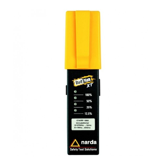
Controls and displays Item Meaning number Threaded bush for tripod or extension Eyelet for fixing the absorber cap to the ESM using nylon cord Yellow absorber cap with fixing clip Isotropic E-field probe Isotropic H-field probe Loudspeaker with earphone connector LEDs for displaying alarm stages and operation (“heartbeat”) Indication of applicable standard and... -
Page 22: Switching On Esm "Radman
Switching on ESM “RadMan” Automatic switch on routine The switch on routine has four main steps. The end of each step and the beginning of the next is signaled by a “beep”. Step 1: LED check Step 2: Battery charge state check ... - Page 23 Switching on ESM “RadMan” After switching on After you switch on the ESM “RadMan”: 1. The LEDs light up briefly one after another, starting with the 12.5% LED. A “beep” is then heard. 2. The battery charge state is indicated. One of the four LEDs lights up.
-
Page 24: Normal Operation
Normal operation Normal operation The E- and H-fields are measured simultaneously during operation. The larger of the two values is displayed. If electromagnetic radiation is present, the ESM “RadMan” indicates the magnitude of the radiation level by means of four LEDs; alarms are additionally signaled by a “beep”... - Page 25 Normal operation This alarm state is indicated by a flashing red LED. The instrument will also emit an audible “beep” twice a second as an additional warning signal. This status is maintained for as long as the ESM “RadMan” continues to measure this level of electromagnetic field strength.
-
Page 26: Esm-30 Only: Data Recorder
ESM-30 only: Data recorder Automatic recording of measured values The measured values are automatically displayed and recorded when the instrument is switched on. A new block of data is started each time the instrument is switched on. Evaluating measurement values The data blocks can be evaluated singly or together on a PC with the aid of the ESM-TS Interface Set, available as an option. -
Page 27: Operational Readiness, Max Hold
Operational readiness, Max Hold The ESM “RadMan” indicates operational readiness every 10 seconds. Operational readiness is indicated by an LED which depends on the electromagnetic radiation that has occurred or been measured. This also allows the magnitude of the highest measured value of electromagnetic radiation to be read off (Max Hold). - Page 28 Operational readiness, Max Hold If the battery capacity is only sufficient for a few more hours of operation, the LED display of operational readiness is replaced by a brief “beep”. Maximum Battery Loud- value display status speaker (Max Hold) 100% 100% Full 100%...
-
Page 29: Applications And Use
Applications and use Areas of use ESM “RadMan” has the following main areas of use. As a warning unit As a rapid tester As a leak locator ESM-30 only: Data recorder General handling instructions Moving the instrument rapidly in an electrostatic field can have a disruptive influence. - Page 30 Applications and use Using ESM as a personal warning unit Application The ESM “RadMan” is worn on the body, preferably by placing it in the breast pocket of your shirt or jacket. Preparation Slide the yellow absorber cap over the end of the instrument.
- Page 31 Applications and use Procedure Stand in your normal working position and slowly turn around through a complete circle. This allows ESM “RadMan” to better detect radiation sources that are behind your back when you are working normally. If the alarm sounds, leave the danger area carefully and without panic.
- Page 32 Preparation Slide the yellow absorber cap over the battery compartment. The “narda” marking is no longer visible. Field reflections caused by the human body are no longer screened. The clip should point to the LED side. If required: Screw the extension rod on to the absorber cap.
- Page 33 Applications and use Procedure Check your environment for sources of electromagnetic radiation. If required: Screw the extension rod on to the absorber cap. After the check, screw the ESM “RadMan” to a non-metallic tripod so that you can work in the area and still be warned of any dangerous electromagnetic radiation levels.
- Page 34 The ESM “RadMan” is used to detect leaks in waveguides. Preparation Slide the yellow absorber cap over the battery compartment. The “narda” marking is no longer visible. The clip should point to the LED side. If required: Screw the extension rod on to the absorber cap.
- Page 35 Applications and use Procedure Hold the ESM “RadMan” at arm’s length. Move the ESM “RadMan” slowly along the waveguide at a relatively large distance from it. If a leak is suspected, slowly move the ESM “RadMan” closer to the suspected location.
- Page 36 Applications and use Using ESM-30 as a data recorder Applications The data recorder records the variation with time of the surrounding electromagnetic radiation. If ESM-30 “RadMan XT” is worn as a warning unit, the exposure of the wearer during the course of the working day can be recorded.
- Page 37 Applications and use Connecting the earphone The earphone supplied can be connected to the ESM “RadMan” so that the audible alarm can still be heard reliably even in areas where high noise levels are present.
- Page 38 Applications and use Reading out measured values The measured values can be read out via the optical interface (A) of the ESM “RadMan”. Data is transferred at a rate of 25 measured values per second. The E-field and H-field values are output separately with much higher accuracy than the LED display.
- Page 39 Applications and use The ESM-TS Interface Set is required to read out the measured values from the ESM “RadMan”. It includes software, a fiber optic cable, and an opto/electric converter with USB connector. The software program allows a wide range of remote control functions and also allows measured values to be read out and saved.
- Page 40 Immediate Vicinity of the Body. Der Einfluß des menschlichen Körpers auf die elektrischen und magnetischen Feldkomponenten in unmittelbarer Nähe des Körpers. “Frequenz”, Vol. 52 (September/October 1998), pp. 170-174 Standards-compliant test of non-ionizing electromagnetic radiation on radar equipment. Author: Dr. Rainer Bitzer See also www.narda-sts.com...
-
Page 41: Checking Field Probe Function
Checking field probe function Checking the function The sensor functions of the ESM “RadMan” can be checked with the aid of a Test Generator (BN 2244/90.38). The H-field and E-field sensors are tested separately. 1. Place the Test Generator in the vicinity of the sensors. - Page 42 Checking field probe function Tip: Make sure that the Test generator batteries are not run down, otherwise the output power of the generator will be insufficient to properly test the field sensors. Although performing an extended self-test with the aid of the Test Generator may permit a fault to be detected, it provides no guarantee that all sensors are measuring correctly, for instance after inexpert handling such as when...
-
Page 43: Repairs, Cleaning
Repairs, Cleaning Repairs ESM “RadMan” may only be repaired by authorized service centers. Please contact your sales office. The casing screws are sealed. If the casing screw seals are damaged, no guarantee claims will be entertained. Cleaning Use only warm water to which a little detergent has been added for cleaning the casing of the ESM “RadMan”. -
Page 44: Calibration
Calibration Calibration Each ESM “RadMan” is calibrated and adjusted before it leaves the factory. Each instrument is calibrated and adjusted separately for the E-field and H-field at the alarm threshold of 100 MHz and at 50% of standard limit value. The E- and H-field sensors are calibrated and adjusted separately. -
Page 45: Changing The Batteries
Changing the batteries Changing the batteries Tip: Only use 1.5 V AAA size alkaline manganese batteries. 1. ESM-30 only: Switch on the ESM-30 “RadMan XT” and monitor the self test (see page 21). If none of the LEDs lights up during the test, you should set the date and time again after you have replaced the batteries. - Page 46 Changing the batteries...
-
Page 47: Specifications
Specifications Miscellaneous All the data specified here is valid under the following conditions unless otherwise stated: ✓ Sinusoidal signals ✓ The instrument is located in the far field region of the source ✓ Ambient temperature: 23°C 3°C ✓ Relative humidity: 25% to 75% The data include all relevant partial errors for calculating the overall error to IEC 359. - Page 48 Specifications Audible warning Built-in loudspeaker Audible alarm if alarm threshold exceeded (50% of relevant standard value) “Beep” repetition rate: 2 Hz starting at 50% of standard, 4 Hz starting at 100% of standard. Frequency response evaluation and limit values according to different standards ESM “RadMan”...
- Page 49 Specifications The limit value traces in the standards exhibit sharp edges. These limit value traces are simulated in the ESM “RadMan” by means of equalizer networks. The frequency response quoted refers to the characteristic of an ideal equalizer circuit containing only 1st order decoupled components.
- Page 50 Specifications ESM-30 only: Data recorder Save interval: The time between consecutive saves of recorded data can be set between 1 second and 3 minutes using the ESM-TS Interface Set. Data set: The r.m.s., maximum and minimum values are calculated continuously during the selected save interval (the interval between measurements is 5 ms, all data are referred to the relevant permitted power flux density in...
- Page 51 Specifications Capacity: The typical capacity is 1600 data sets, corresponding to about 27 hours operation at a save interval of 1 minute. The oldest recorded values will be overwritten if the memory capacity is exceeded (ring memory). Built-in clock: Date and time data are provided from a built-in clock module, which is powered from the normal batteries.
- Page 52 Specifications ESM-30 only: The following additional functions are available: Read out values recorded in the data recorder. The transfer time for all the data when the data recorder is completely full is less than 5 minutes. Select the save interval: The time between consecutive saves of recorded data can be set in several steps between 1 second and 3 minutes.
-
Page 53: General Information
General information Power supply Batteries ....2 size AAA, alkaline manganese primary cells Operating time ... . . typ. 200 hours (without alarms, interface cover closed) Battery... - Page 54 General information Declaration of origin Country of origin: Germany Ambient temperature Nominal range of use ..-10°C to 55°C Storage and transport ..-40°C to 70°C Environment classes IEC 60721-3-2 class 7K2...
-
Page 55: Esm-10 Declaration Of Conformity
ESM-10 Declaration of Conformity... -
Page 56: Esm-20 Declaration Of Conformity
ESM-20 Declaration of Conformity... -
Page 57: Esm-30 Declaration Of Conformity
ESM-30 Declaration of Conformity... -
Page 58: Instrument Versions
Instrument versions ESM-10 “RadMan Mobile” Standard Frequency range Part number H-field E-field FCC 96-326, Aug. 50 MHz 50 MHz 2252/02 1996, occupational 1 GHz 6 GHz ICNIRP, 1998, 50 MHz 50 MHz 2252/06 occupational 1 GHz 6 GHz The frequency range values printed on the in- strument are applicable in each case. - Page 59 Instrument versions ESM-20 “RadMan” Standard Frequency Part Part range number number fast re- slow re- H-field E-field sponse sponse BGV B11, 2001, 1 MHz 1 MHz 2250/01 2250/51 EXP. 1 1 GHz 40 GHz FCC 96-326, 3 MHz 3 MHz 2250/02 2250/52 Aug.
- Page 60 Instrument versions ESM-30 “RadMan XT” Standard Frequency Part Part range number number fast re- slow re- H-field E-field sponse sponse BGV B11, 2001, 1 MHz 1 MHz 2251/51 2251/01 EXP. 1 1 GHz 40 GHz FCC 96-326, 3 MHz 3 MHz –...
-
Page 61: Accessories
Accessories Standard accessories Earphone for audible alarm 2250/92.01 Battery, dry-cell 2250/92.10 Belt bag 2250/92.06 Operating manual German 2250/98.01 English 2250/98.21 Optional accessories 27 MHz Test Generator 2244/90.38 Extension rod 2250/92.02 ESM-TS Interface Set 2251/90.51 Hardcase 2250/92.03 Accessory kit 2250/92.05 (handle, storage case) Tripod benchtop 0.16 m 2244/90.32... - Page 62 Phone +39 02 26 998 71 Fax +39 02 26 998 700 nardait.support@L-3com.com www.narda-sts.it ® The name and logo are registered trade- marks of Narda Safety Test Solutions GmbH and L3 Communications Holdings, Inc. Pro- prietary names are the trademarks of their re- spective owners.
- Page 63 The key to this diagram is shown on the inside front cover. See also page 19.
- Page 64 ESM “RadMan” BN 2250/xx, BN 2251/xx and BN 2252/xx Brief operating instructions After switching on 1. The LEDs light up briefly one after another, starting with the 12.5% LED. A “beep” is then heard. 2. The battery charge state is indicated. One of the four LEDs lights up.