Table of Contents
Advertisement
Quick Links
Installation, Operation, and Maintenance
Remote Air-Cooled Condensers
Outdoor Cooling Systems
Only qualified personnel should install and service the equipment. The installation, starting up, and servicing of
heating, ventilating, and air-conditioning equipment can be hazardous and requires specific knowledge and training.
Improperly installed, adjusted or altered equipment by an unqualified person could result in death or serious injury.
When working on the equipment, observe all precautions in the literature and on the tags, stickers, and labels that are
attached to the equipment.
December 2020
SAFETY WARNING
SS-SVX006C-EN
Advertisement
Table of Contents

Related Manuals for Trane TR-SCS Series

Summary of Contents for Trane TR-SCS Series
- Page 1 Installation, Operation, and Maintenance Remote Air-Cooled Condensers Outdoor Cooling Systems SAFETY WARNING Only qualified personnel should install and service the equipment. The installation, starting up, and servicing of heating, ventilating, and air-conditioning equipment can be hazardous and requires specific knowledge and training. Improperly installed, adjusted or altered equipment by an unqualified person could result in death or serious injury.
- Page 2 PRIOR to Practices servicing the unit. NEVER PERFORM ANY Trane believes that responsible refrigerant practices are SWITCHING, DISCONNECTING, OR VOLTAGE TESTING WITHOUT PROPER ELECTRICAL PPE AND important to the environment, our customers, and the air conditioning industry.
- Page 3 Copyright This document and the information in it are the property of Trane, and may not be used or reproduced in whole or in part without written permission. Trane reserves the right to revise this publication at any time, and to make changes to its content without obligation to notify any person of such revision or change.
-
Page 4: Table Of Contents
Table of Contents Model Number Descriptions Refrigerant Characteristics ....21 ....5 Pressure/Temperature Settings ..21 Introduction . -
Page 5: Model Number Descriptions
Model Number Descriptions Example using model TR-SCS Series Condensers TR-SCS Series Micro-Channel Condenser TR-SCS-MC-056-D-LN-F-1: Digit 1,2,3,4,5— Unit • Condenser Section with Micro- Configuration Digit 1,2,3,4,5,6,7 — Unit Channel Coil TR-SCS = Series Condenser Configuration (SCS-MC, digits 1,2,3,4,5,6,7) TR-SCS-MC = Condenser Section with... -
Page 6: Introduction
Trane Air-cooled Condensers are designed to reject heat motors. from refrigerant based cooling equipment. Any use beyond this is deemed to be not intended. Trane is not • Unit mounted, weather resistant control enclosure liable for any damage resulting from improper use. The with lockable service disconnect switch. -
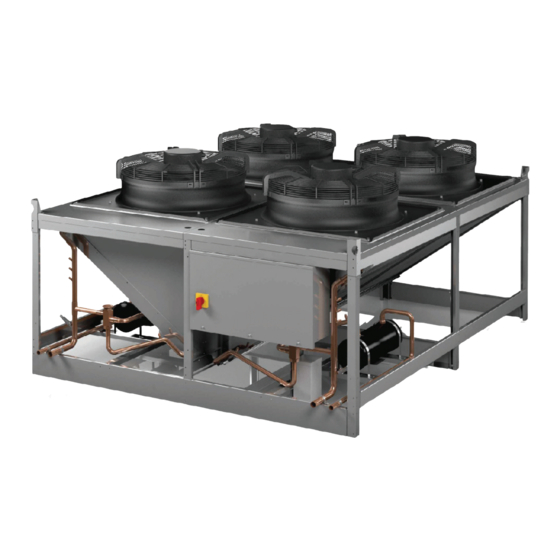
Page 7: General Design
VOID THE WARRANTY. Fan with Finger Guard General Design Trane TR-SCS series remote air-cooled condensers are Lifting Eye housed in an aluminum frame cabinet and are rated for outdoor use. The figures that follow depict the two types of condensers and identifies the major components. -
Page 8: Head Pressure Controls
(A/C) units. Contact pressure. The fan speed control is a continual modulation Trane Product Support for assistance. of the motor’s speed. The condenser fan speed controller monitors the refrigerant discharge pressure and as On single circuit condensers, each fan is controlled with its discharge pressure rises, the fan speed increases. - Page 9 Introduction When ambient temperature drops, the discharge pressure This method of controlling head pressure allows the drops also. When the discharge pressure drops, the head condenser fan to run continuously. While the fan is pressure control valve diverts discharge gas away from running, the flooded head pressure control valve the condenser to the receiver.
-
Page 10: Installation
To avoid dropping of unit, reposition lifting point if unit is not level. Trane ships all equipment FOB factory. Trane is not liable for any equipment damage while in transit. Trane can assist in the claim filing process with the freight carrier. -
Page 11: Mounting And Placement
Installation Mounting and Placement Figure 4. Rigging Outdoor, air-cooled condensers are designed for mounting to a flat surface. Condenser(s) must not be near steam, hot air or fume exhausts. Avoid overhead obstructions. Ensure the unit is not located above or near noise sensitive areas. -
Page 12: Receiver
Installation The clearance around the unit to the nearest wall or Figure 8. Receiver assembly obstruction should be at least 1 time’s (1×) the unit’s width to ensure adequate airflow to the coil(s) (see Figure 5 Outlet Rotalock Valve (4X) with 7/8 in. Figure 6). -
Page 13: Refrigerant Line Sizing
Installation silver is recommended. General purpose silver brazing Note: The size of the condenser pipe connections does alloy with 45% silver is recommended for brazing not indicate the size of the refrigerant lines to be dissimilar metals. used. In cases where the pipe size doesn’t match the size of the connection, reducing fittings must be Wrap wet rags around the pipes between the areas to be used to transition between the connection and the... - Page 14 Installation Riser #2 should be sized in such way that the inside Figure 10. Dual riser piping diameter of riser #1 and #2 will together have a combined area allowing for a flow velocity that’s suitable to carry the INVERTED TRAP refrigerant oil to the condenser during peak load PITCH 1/4 INCH FOR EVERY 10 FEET OF RUN conditions.
-
Page 15: Head Pressure Control Valve Installation (Tr-Scs Condenser Only)
Installation Main Power and Control Wiring Table 4. Pressure drops Systems equipped with a remote condenser require field Pressure Drop in wiring (see Figure 10, p. 14). The installer must provide Refrigerant Type PSI/ft (Risers) main power wiring to the remote condenser control box. R407C 0.47 The condenser is provided with main power and control... - Page 16 Installation Figure 11. Field wiring ELECTRIC BOX MAIN POWER SUPPLY REMOTE AIR COOLED CONDENSER OPTIONAL CONTROL WIRES (QUANTITY VARIES) RECEIVER HEATER WIRES (IF APPLICABLE -30° F) INTERCONNECTING FIELD WIRING (TO BE INSTALLED IN ACCORDANCE WITH NFPA 70, N.E.C.) Identify the options that were purchased with your system Figure 12.
-
Page 17: System Charging
Installation liquid within a contained system. The composition of System Charging liquid R407C refrigerant remains relatively constant, however, the refrigerant vapor tends to separate into its Refrigerant charging pressures vary depending on the component parts even when circulating. type of refrigerant used in the unit. Before charging, check the unit nameplate to confirm the type of refrigerant to Estimating Refrigerant Charge use. -
Page 18: Preparing System For Charging
Installation Table 6. TR-SCS-MC condenser refrigerant charge weights (lb) R407C Charge R410A Charge R407C Charge (Condenser with R410A Charge (Condenser with TR-SCS Model Receiver) Receiver) Number -20°F Ambient & -30°F Ambient -20°F Ambient & Higher -30°F Ambient Higher 015-S 018-S 031-S 031-D* 035-S... -
Page 19: Refrigerant Charging Procedures
Allow the system to stand for two hours Information for you on the Warranty Registration and with the dry nitrogen charge. This gives time for the Start-up Checklist and ensure it is filed with Trane for your nitrogen molecules to disperse in the system warranty protection. - Page 20 Installation charge will be performed by introducing liquid refrigerant (R407C or R410A) to the discharge side of the compressor NOTICE or an available liquid line port with the A/C unit turned Off. Compressor Damage! 1. Bleed air from hoses and break the vacuum by Failure to follow instructions below could result in supplying liquid refrigerant (R407C or R410A) to the compressor failure and/or reduced compressor life.
-
Page 21: Refrigerant Characteristics
Installation The head pressure control valve setting is printed on the Fan 3 - 340 cut-in; 260 cutout Fan valve. This setting is the lowest head pressure that will be Fan 4 - 345 cut-in; 265 cutout maintained during unit operation. Add refrigerant to the EC Fan (Fan 1 on TR-SCS Condenser) - 240 psig start;... - Page 22 Installation R410A Table 10. refrigerant vapor pressure (continued) R407C Table 9. refrigerant vapor pressure R410A Refrigerant R407C Refrigerant Temperature (°F) Pressure (psid) Temperature (°F) Pressure (psid) Saturated Evaporating Temperature Saturated Evaporating Temperature (Dew Point Saturated Vapor) 37.9 40.1 42.3 44.7 47.1 49.6 52.1...
- Page 23 Installation 1. The refrigerant then flows to the condenser coil. The high temperature, high-pressure gas from the compressor is cooled by the flow of air through the condenser coil and is condensed into a high-pressure liquid. 2. For cold weather applications using flooded head pressure control, the low temperature high-pressure liquid refrigerant flows to a receiver.
-
Page 24: Startup And Commissioning
Operational Description When used with a Trane indoor evaporator unit, the A/C system compressor starts then the condenser fan(s) start. Operation of the condenser fans is dependent on the head pressure control method used. -
Page 25: Maintenance
(see Appendix A) to record periodic general dirt and oily film. Use wire brush, sandcloth or sandpaper maintenance inspections. For assistance, contact Trane and wipe the area with clean, dry cloths. Protect nearby Product Support. Ensure your adherence to all safety parts from heat damage by wrapping with water-soaked statements while performing any type of maintenance. -
Page 26: Troubleshooting
Maintenance contactors and wiring. Contactors should be examined and replaced if the contact pads are worn or pitted. Troubleshooting WARNING Hazardous Service Procedures! Failure to follow all precautions in this manual and on the tags, stickers, and labels could result in death or serious injury. -
Page 27: Recommended Maintenance
Maintenance Symptoms Probable Cause Recommendation Incorrect phasing or voltage Correct phase or voltage input Power failure Check power source, power input and fuses. Check control Unit Fails to Start cables and connections. Overload protection tripped Check pressure/temperature operating switches and motor. -
Page 28: Product Support
Product Support Product Support provides aftermarket technical and field Obtaining Warranty Parts support, warranty authorization and part sales to contractors and end users. Factory authorized services are A support technician will provide troubleshooting available by request and include: assistance over the telephone. •... -
Page 29: Installation Checklist
Appendix A Installation Checklist Table 11. Installation checklist Tasks Comments Proper clearances for service access have been maintained around equipment. Equipment is level and mounting fasteners are tight. If required, piping completed to refrigerant or coolant loop. All field installed piping leak tested. If required, refrigerant charge added. - Page 32 For more information, please visit trane.com or tranetechnologies.com. Trane has a policy of continuous product and product data improvement and reserves the right to change design and specifications without notice. We are committed to using environmentally conscious print practices.