
Related Manuals for National Instruments NI Vision NI PCI-1424


Summary of Contents for National Instruments NI Vision NI PCI-1424
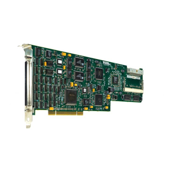
- Page 1 NI Vision NI PCI-1424 User Manual High-Quality Digital Image Acquisition Device NI PCI-1424 User Manual February 2007 371869D-01...
- Page 2 For further support information, refer to the Technical Support and Professional Services appendix. To comment on National Instruments documentation, refer to the National Instruments Web site at ni.com/info and enter the info code feedback. © 1999–2007 National Instruments Corporation. All rights reserved.
- Page 3 Instruments Corporation. National Instruments respects the intellectual property of others, and we ask our users to do the same. NI software is protected by copyright and other intellectual property laws. Where NI software may be used to reproduce software or other materials belonging to others, you may use NI software only to reproduce materials that you may reproduce in accordance with the terms of any applicable license or other legal restriction.
- Page 4 These classes are known as Class A (for use in industrial-commercial locations only) or Class B (for use in residential or commercial locations). All National Instruments (NI) products are FCC Class A products. Depending on where it is operated, this Class A product could be subject to restrictions in the FCC rules. (In Canada, the Department of Communications (DOC), of Industry Canada, regulates wireless interference in much the same way.) Digital...
- Page 5 Conventions The following conventions are used in this manual: <> Angle brackets that contain numbers separated by an ellipsis represent a range of values associated with a bit or signal name—for example, AO <3..0>. » The » symbol leads you through nested menu items and dialog box options to a final action.
-
Page 6: Table Of Contents
Chapter 1 Introduction About the NI 1424 ......................1-1 Software Overview ......................1-2 NI-IMAQ Driver Software ................1-2 National Instruments Application Software ............1-3 Vision Builder for Automated Inspection.........1-3 Vision Development Module ............1-3 Integration with DAQ and Motion Control .............1-4 Chapter 2 Hardware Overview Functional Overview......................2-1... - Page 7 Contents Glossary Index NI PCI-1424 User Manual ni.com...
-
Page 8: About The Ni 1424
Acquisition Software, which includes NI-IMAQ, the National Instruments driver software you can use to directly control the NI 1424 and other National Instruments image acquisition devices. Using NI-IMAQ, you can quickly and easily start your applications without having to program the device at the register level. -
Page 9: Software Overview
Vision Builder for Automated Inspection (AI)—for configuring solutions to common inspection tasks • National Instruments Vision Development Module—for more customized control over hardware and algorithms The following sections provide an overview of the driver software and the application software. For detailed information about individual software packages, refer to the documentation specific to the package. -
Page 10: National Instruments Application Software
Chapter 1 Introduction National Instruments Application Software Vision Builder for Automated Inspection NI Vision Builder for Automated Inspection (AI) is configurable machine vision software that you can use to prototype, benchmark, and deploy applications. Vision Builder AI does not require programming, but is scalable to powerful programming environments. -
Page 11: Integration With Daq And Motion Control
Integration with DAQ and Motion Control Platforms that support NI-IMAQ also support NI-DAQ and a variety of National Instruments DAQ devices. This allows for integration between image acquisition devices and DAQ devices. Use National Instruments high-performance stepper and servo motion... -
Page 12: Hardware Overview
The NI 1424 features a high-speed data path optimized for the reception and formatting of video data from digital monochrome and color cameras. The block diagram in Figure 2-1 illustrates the key functional components of the NI 1424. © National Instruments Corporation NI PCI-1424 User Manual... -
Page 13: Signaling
Chapter 2 Hardware Overview Synchronous Dynamic RAM UART Memory Data Data Data IMAQ SDRAM Data Memory Interface PCI Interface Pixel Clock and Camera Enables Scatter-Gather Enables Differential/ DMA Controllers Converter Pixel Advanced Clock Acquisition, Triggering ROI, and Control and Timing Camera Control External Triggers... -
Page 14: Multiple-Tap Data Formatter
The NI 1424 comes with 16 MB of onboard high-speed synchronous dynamic RAM (SDRAM). You can purchase additional SO-DIMM memory upgrades from National Instruments. SO-DIMM upgrades are available in 64 MB and 128 MB densities. The NI 1424 can also use the onboard RAM as a first-in first-out (FIFO) buffer so that in some instances, the NI 1424 can capture images larger than the amount of RAM on the device. -
Page 15: High-Speed Timing
Chapter 2 Hardware Overview High-Speed Timing The high-speed timing circuitry on the NI 1424, built from high-speed counters, allows you to specify or generate precise, real-time control signals. You can map the output of this circuitry to a trigger line to provide accurate pulses and pulse trains. -
Page 16: Acquisition Window Control
In interlaced mode, the NI 1424 combines the odd and even fields into one contiguous frame for analysis. In non-interlaced mode, each field is treated as an independent frame. © National Instruments Corporation NI PCI-1424 User Manual... -
Page 17: Signal Connections
To access these connections, you can build your own custom cable or use one of the optional cables from National Instruments. Refer to the National Instruments Web site, , for the latest Note ni.com/vision information on optional cables and the cameras they support. - Page 18 Chapter 3 Signal Connections Figure 3-1 shows the pinout of the 100-pin SCSI-type connector. Data0+ Data16+ Data0– Data16– Data1+ Data17+ Data1– Data17– Data2+ Data18+ Data2– Data18– Data3+ Data19+ Data3– Data19– Data4+ Data20+ Data4– Data20– Data5+ Data21+ Data5– Data21– Data6+ Data22+ Data6–...
-
Page 19: Signal Description
The NI 1424 uses the Pixel Clock input as a reference clock to latch the incoming video data in either TTL or differential format. GND is a direct connection to digital ground on the NI 1424. © National Instruments Corporation NI PCI-1424 User Manual... -
Page 20: Technical Support And Professional Services
Technical Support and Professional Services Visit the following sections of the National Instruments Web site at for technical support and professional services: ni.com • Support—Online technical support resources at ni.com/support include the following: – Self-Help Resources—For answers and solutions, visit the... - Page 21 Appendix A Technical Support and Professional Services • Calibration Certificate—If your product supports calibration, you can obtain the calibration certificate for your product at ni.com/calibration If you searched and could not find the answers you need, contact ni.com your local office or NI corporate headquarters. Phone numbers for our worldwide offices are listed at the front of this manual.
- Page 22 (2) Collecting and measuring the same kinds of electrical signals with A/D or DIO devices plugged into a computer, and possibly generating control signals with D/A and/or DIO devices in the same computer. © National Instruments Corporation NI PCI-1424 User Manual...
- Page 23 Glossary Direct memory access. A method by which data can be transferred to and from computer memory from and to a device or memory on the bus while the processor does something else; DMA is the fastest method of transferring data to/from computer memory. driver Software that controls a specific hardware device, such as an image acquisition device.
- Page 24 See buffer. NI-IMAQ Driver software for National Instruments image acquisition hardware. NVRAM Nonvolatile RAM. RAM that is not erased when a device loses power or is turned off. Peripheral Component Interconnect. A high-performance expansion bus architecture originally developed by Intel to replace ISA and EISA.
- Page 25 Glossary scatter-gather DMA A type of DMA that allows the DMA controller to reconfigure on-the-fly. SDRAM Synchronous dynamic RAM. SO-DIMM Small outline dual inline memory module. A stream of pixels from a camera. Some cameras send multiple streams, or taps, of data over a cable simultaneously to increase transfer rate. transfer rate The rate, measured in bytes/s, at which data is moved from source to destination after software initialization and set up operations.
- Page 26 2-3 diagnostic tools (NI resources), A-1 help, technical support, A-1 DMA controllers, 2-4 high-speed timing circuitry, 2-4 documentation conventions used in the manual, v NI resources, A-1 drivers (NI resources), A-1 © National Instruments Corporation NI PCI-1424 User Manual...
- Page 27 3-1 multiple-tap data formatter, 2-3 pin assignments (figure), 3-2 signal description (table), 3-3 SIN signal (table), 3-3 software National Instruments support and NI resources, A-1 services, A-1 NI Vision Development Module, 1-3 NI 1424 programming choices block diagram, 2-2...
- Page 28 Index technical support, A-1 Web resources, A-1 training and certification (NI resources), A-1 trigger control and mapping circuitry, 2-3 trigger controlled start conditions, 2-4 troubleshooting (NI resources), A-1 © National Instruments Corporation NI PCI-1424 User Manual...