Table of Contents
Advertisement
Quick Links
Advertisement
Table of Contents

Related Manuals for Haier IT9002


Summary of Contents for Haier IT9002
- Page 1 Service Manual...
-
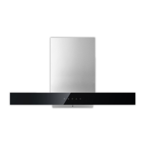
Page 2: Cooker Hood
IT9002 Cooker Hood INSTALLATION AND USER’S MANUAL... -
Page 3: Safety Precaution
SAFETY PRECAUTION • mportant! Always switch off the electricity supply at the mains during installation and maintenance such as light bulb replacement. • he cooker hood must be installed in accordance with the installation instructions and all measurements followed. • ll installation work must be carried out by a competent person or qualified electrician. -
Page 4: Maintenance
SAFETY PRECAUTION • aution: The appliance and its accessible parts can become hot during operation. Be careful to avoid touching the heating elements. Children younger than 8 years old should stay away unless they are under permanent supervision. – here shall be adequate ventilation of the room when the range hood is used at the same time as appliances burning gas or other fuels. - Page 5 Parts identification Parts Name (1) Extraction hood (2) Chimney section (including upper and lower parts) (3) Hose connector (4) Upper wall bracket (5) Lower wall bracket (6) ø 4mm x 10mm Screw (6 pcs) (7) Washer (2 pcs) (8) Wall plug (8 pcs) (9) ø...
- Page 6 Wattage(Total) 202W Motor 200W Filter 1xAluminium Filter Light 1x2W LED lights Noise Level 68dB Speed control 3 Speed control Type of switch Touch switch...
-
Page 7: Installation
Installation (for venting outside) When the cooker hood is to be installed above an electric hob or a gas hob, the minimum distance between the hob and cooker hood must exceed 700mm. If the instructions for installation for the gas hob specify a greater distance, this has to be taken into account. - Page 8 Installation (for venting outside) Tools required Mark wall as required (see Fig. 6) Fig. 5 Fig. 6 Drill holes for mounting the body. Fix support plate on the wall by screws with expanding plugs. 10mm Fig. 8 Fig. 7 Secure hood (tighten all screws). Fit ducting adaptor.
- Page 9 IMPORTANT SAFETY WARNING: ONLY USE THE SCREWS PROVIDED WITH THE RANGE HOOD TO MOUNT THE DUCTING ADAPTOR. THE USE OF LONGER SCREWS MAY CAUSE DAMAGE TO THE INTERNAL WIRING WHICH WILL NOT BE COVERED BY THE WARRANTY. Fix ducting (seal joint by 3 pieces ST3X8). Fig.
- Page 10 If you do not have an outlet for exhausting air, the exhaust hose (part [10]) is not required, and the installation is similar to the one shown in the section "Installation (for venting outside)". Air is vented back into the kitchen through the opening of the cooker hood, this circulating air mode requires the use of the carbon filter (part [11]) to remove odors.
-
Page 11: Using Your Cooker Hood
Using your Cooker hood For best performance, you should switch on the extractor 15 minutes before starting to cook and leave it to run for approximately 15 minutes after the end of cooking. Fig. 13 ON/OFF Key/Delay Timer: • Press the key to turn on/o the extractor. -
Page 12: Care And Maintenance
Care and Maintenance IMPORTANT : DO NOT PERFORM MAINTENANCE OR CLEANING OF THE COOKER HOOD WITHOUT FIRST SWITCHING OFF THE ELECTRICITY SUPPLY. Cleaning You should use a nonabrasive cleaner. Any abrasive cleaner (including Cif) will scratch the surface and could erase the control panel markings. You can clean your cooker hood effectively by simply using a dilute solution of water and mild detergent and then dry it with a clean cloth. - Page 13 Information for cooker hood ENVIRONMENTAL PROTECTION: This product is marked with the symbol on the selective sorting of waste electronic equipment. This means that this product must not be disposed of with household waste but must be supported by a system of selective collection in accordance with Directive 2002/96/EC.
-
Page 14: Troubleshooting
Troubleshooting Failure Root cause Corrective action 1. Not plug-in or poor plug- 1. Plug-in perfect. power 2. Connect with power supply or 2. Power socket is no contact electrician for after power. service. 3. Power supply dose not 3. Replace fuse or call connect with fuse or fuse electrician for after service. - Page 15 1. Oil cup Remove oil cup from card slot based on horizontal. Filter Remove screws to take out filter. 3. Hand-fasten nut Clockwise rotate the nut to remove it. Remove fan.
- Page 16 5. Chimney Remove 4 screws, take out chimneys. Cover sheet...
- Page 17 Remove 4 screws to take out cover sheet. 7. Maintainence cover Remove 12 screws to take out maintainence cover. Then repair fan and motor. 8. Remove 8 screws from damper and 4 screws from air outlet. Then from reverse side of body to remove one M5 screw.
- Page 18 9.LED light and switch control wire Use flat screwdriver to remove LED light. Disconnect all responding wire connectors for replacement. 10. Switch...
- Page 19 Remove cover sheet and screws to take out switch. Wiring Diagram...