Table of Contents
Advertisement
Quick Links
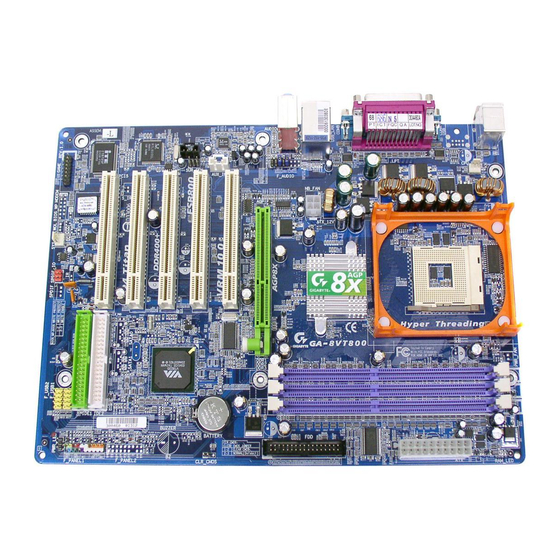
When you installing AGP card, please make sure the following
notice is fully understood and practiced. If your AGP card has
"AGP 4X/8X(1.5V) notch"(show below), please make sure your AGP
card is AGP 4X/8X (1.5V).
AGP 4X/8X notch
Caution: AGP 2X(3.3V) card is not supported by VIA PT800. You might
experience system unable to boot up normally. Please insert an AGP
4X/8X (1.5V) card
Example 1: Diamond Vipper V770 golden finger is compatible with
2X/4X mode AGP slot. It can be switched between AGP 2X(3.3V) or 4X
(1.5V) mode by adjusting the jumper. The factory default for this card is
2X(3.3V).
The GA-8VT800-P motherboards might not function properly, if you install
this card without switching the jumper to 4X(1.5V) mode in it.
Example 2: Some ATi Rage 128 Pro graphics cards made by
"Power Color", the graphics card manufacturer & some SiS 305 cards,
their golden finger is compatible with 2X/4X mode AGP slot, but they
support 2X(3.3V) only. The GA-8VT800-P motherboards might not function
properly, If you install this card in it.
Note : Although Gigabyte's AG32S(G) graphics card is based on
ATi Rage 128 Pro chip, the design of AG32S(G) is compliance
with AGP 4X(1.5V) specification. Therefore, AG32S (G)will work
fine with VIA PT800 based motherboards.
Advertisement
Table of Contents

Related Manuals for Gigabyte GA-8VT800


Summary of Contents for Gigabyte GA-8VT800
- Page 1 (1.5V) mode by adjusting the jumper. The factory default for this card is 2X(3.3V). The GA-8VT800-P motherboards might not function properly, if you install this card without switching the jumper to 4X(1.5V) mode in it. Example 2: Some ATi Rage 128 Pro graphics cards made by "Power Color", the graphics card manufacturer &...
- Page 2 M The author assumes no responsibility for any errors or omissions that may appear in this document nor does the author make a commitment to update the information contained herein. M Third-party brands and names are the property of theirrespective owners.
-
Page 3: Declaration Of Conformity
EN 60335 Safety of household and similar electrical appliances (Stamp) Mother Board GA-8VT800 o EN 61000-3-2* Disturbances in supply systems cause T EN 60555-2 by household appliances and similar electrical equipment “Harmonics” o EN 61000-3-3*... - Page 4 Phone/Fax No: hereby declares that the product Product Name: Motherboard Model Number: GA-8VT800 Conforms to the following specifications: FCC Part 15, Subpart B, Section 15.107(a) and Section 15.109 (a),Class B Digital Device Supplementary Information: This device complies with part 15 of the FCC Rules. Operation is...
- Page 5 GA-8VT800-P P4 Titan Series Motherboard USER'S MANUAL Pentium ® 4 Processor Motherboard Rev. 1002 12ME-8VT800P-1002...
-
Page 6: Table Of Contents
Item Checklist ... 4 WARNING! ... 4 Chapter 1 Introduction ... 5 Features Summary ... 5 GA-8VT800-P Motherboard Layout ... 7 Block Diagramt ... Chapter 2 Hardware Installation Process ... 11 Step 1: Install the Central Processing Unit (CPU) ... 12 Step 1-1 : CPU Installation ... - Page 7 Power Management Setup ... 43 PnP/PCI Configurations ... 45 PC Health Status ... 46 Frequency/Voltage Control ... 48 Load Fail-Safe Defaults ... 50 Load Optimized Defaults ... 51 Set Supervisor/User Password ... 52 Save & Exit Setup ... 53 Exit Without Saving ... 54 Chapter 4 Technical Reference ...
-
Page 8: Item Checklist
GC-SATA Card (Optional) (Manual; SATA cable x1; Power cable x 1) Computer motherboards and expansion cards contain very delicate Integrated Circuit (IC) chips. To protect them against damage from static electricity, you should follow some precautions whenever you work on your computer. -
Page 9: Chapter 1 Introduction
Chapter 1 Introduction Features Summary — 30.5cm x 21.4cm ATX size form factor, 4 layers PCB. Form Factor — Socket 478 for Intel — Support Intel — Support Intel — Intel Pentium — 2nd cache depends on CPU — Chipset VIA PT800 HOST/AGP/Controller Chipset —... - Page 10 Whether your system can run under these specific bus frequencies properly will depend on your hardware configurations, including CPU, Chipsets, SDRAM, Cards….etc. GA-8VT800-P Motherboard Realtek ALC655 CODEC Supports Jack Sensing function Line Out / 2 front speaker Line In / 2 rear speaker(by s/w switch) Mic In / center&...
-
Page 11: Ga-8Vt800-P Motherboard Layout
GA-8VT800-P Motherboard Layout KB_MS CPU_FAN SOCKET478 ATX_12V F_AUDIO CODEC AUX_IN CD_IN SUR_CEN ITE8705F BIOS GAME SYS_FAN VIA PT800 PCI1 PCI2 VT8237 PCI3 PCI4 S_ATA0 S_ATA1 IDE2 PCI5 IDE1 F_USB1 SPDIF_IO PWR_LED F_USB2 - 7 - Introduction... -
Page 12: Block Diagram
5 PCI PCICLK (33MHz) 2 SATA AC97 Ports CODEC PCICLK (33MHz) USBCLK (48MHz) 14.318 MHz 33 MHz 24 MHz GA-8VT800-P Motherboard Pentium 4 CPUCLK+/- (100/133/200MHz) Socket 478 System Bus 400/533/800MHz 266/333/400MHz GCLKNB VIA PT800 HCLK+/- (100/133/200MHz) 66MHz 33 MHz 14.318 MHz... - Page 13 - 9 - Hardware Installation Process...
- Page 14 GA-8VT800-P Motherboard - 10 -...
-
Page 15: Chapter 2 Hardware Installation Process
Chapter 2 Hardware Installation Process To set up your computer, you must complete the following steps: Step 1- Install the Central Processing Unit (CPU) Step 2- Install memory modules Step 3- Install expansion cards Step 4- Connect ribbon cables, cabinet wires, and power supply Step 4 Step 4 Step 3... -
Page 16: Step 1: Install The Central Processing Unit (Cpu)
1. Angling the rod to 65-degree maybe feel a kind of tight, and then continue pull the rod to 90-degree when a noise "cough" made. Pin1 indicator 3. CPU Top View GA-8VT800-P Motherboard Socket Actuation Lever 2. Pull the rod to the 90-degree directly. -
Page 17: Step 1-2 : Cpu Heat Sink Installation
Step 1-2 : CPU Cooling Fan Installation Before installing the CPU Cooling Fan , adhere to the following warning: 1. Please use Intel approved cooling fan. 2. We recommend you to apply the thermal tape to provide better heat conduction between your CPU and cooling fan. -
Page 18: Step 2: Install Memory Modules
Support Unbuffered DDR DIMM Sizes type: 64 Mbit (2Mx8x4 banks) 64 Mbit (1Mx16x4 banks) 128 Mbit(2Mx16x4 banks) 256 Mbit(8Mx8x4 banks) 512 Mbit(16Mx8x4 banks) 512 Mbit(8Mx16x4 banks) Total System Memory (Max3GB) GA-8VT800-P Motherboard Notch 128 Mbit(4Mx8x4 banks) 256 Mbit(4Mx16x4 banks) - 14 -... - Page 19 1. The DIMM slot has a notch, so the DIMM memory module can only fit in one direction. 2. Insert the DIMM memory module vertically into the DIMM slot. Then push it down. 3. Close the plastic clip at both edges of the DIMM slots to lock the DIMM module.
-
Page 20: Step 3: Install Expansion Cards
7. Power on the computer, if necessary, setup BIOS utility of expansion card from BIOS. 8. Install related driver from the operating system. AGP Card GA-8VT800-P Motherboard Please carefully pull out the small white- drawable bar at the end of the AGP slot when you try to install/ Uninstall the AGP card. -
Page 21: Step 4: Connect Ribbon Cables, Cabinet Wires, And Power Supply
(6 pin Female) v/x USB Connector USB2 USB0 USB3 USB1 GA-8VT800-P Motherboard Ø This connector supports standard PS/2 keyboard and PS/2 mouse. Ø Before you connect your device(s) into USB connector(s), please make sure your device(s) such as USB keyboard,mouse, scanner, zip, speaker..etc. - Page 22 MIC In(Center and Subwoofer) If you want the detail information for 2-/4-/6-channel audio setup installation, please refer to page 74. GA-8VT800-P Motherboard Ø This connector supports 2 standard COM ports and 1 Parallel port. Device like printer can be connected to Parallel port; mouse and modem etc.
-
Page 23: Step 4-2: Connectors & Jumper Setting Introduction
Step 4-2: Connectors & Jumper Setting Introduction 1) ATX_12V 2) ATX 3) CPU_FAN 4) SYS_FAN 5) S_ATA0/S_ATA1 6) IDE1/IDE2 7) FDD 8) RAM_LED 9) F_PANEL 10) PWR_LED 11) BAT 12) F_AUDIO 13) SUR_CEN 14) CD_IN 15) AUX_IN 16) SPDIF_IO 17) F_USB1/F_USB2 18) GAME 19) CLR_CMOS - 19 -... - Page 24 2) ATX (ATX Power) AC power cord should only be connected to your power supply unit after ATX power cable and other related devices are firmly connected to the mainboard. GA-8VT800-P Motherboard Pin No. Definition +12V +12V Pin No.
- Page 25 3) CPU_FAN (CPU FAN Connector) Please note, a proper installation of the CPU cooler is essential to prevent the CPU from running under abnormal condition or damaged by overheating.The CPU fan connector supports Max. current up to 600 mA. 4) SYS_FAN (System FAN Connector) This connector allows you to link with the cooling fan on the system case to lower the system temperature.
- Page 26 You can connect the Serial ATA device to this connector, it provides you high speed transfer rates (150MB/sec). 6) IDE1/ IDE2 (IDE1/IDE2 Connector) Please connect first harddisk to IDE1 and connect CDROM to IDE2. The red stripe of the ribbon cable must be the same side with the Pin1. GA-8VT800-P Motherboard Pin No. Definition SATA0 SATA1...
- Page 27 7) FDD (Floppy Connector) Please connect the floppy drive ribbon cables to FDD. It supports 360K,720K,1.2M,1.44M and 2.88Mbytes floppy disk types. The red stripe of the ribbon cable must be the same side with the Pin1. 8) RAM_LED Do not remove memory modules while RAM LED is on. It might cause short or other unexpected damages due to the stand by voltage.
- Page 28 (Blue) SPEAK (Speaker Connector) (Amber) RES (Reset Switch) (Green) PW (Soft Power Connector) (Red) MSG(Message LED/Power/ Sleep LED)(Yellow) NC( Purple) GA-8VT800-P Motherboard 20 19 Speaker Connector Soft Power Connector IDE Hard Disk Message LED/Power/ Active LED Sleep LED Pin 1: LED anode(+)
- Page 29 10)PWR_LED PWR_LED is connect with the system power indicator to indicate whether the system is on/off. It will blink when the system enters suspend mode. If you use dual color LED, power LED will turn to another color. 11) BAT (Battery) If you want to erase CMOS...
- Page 30 13) SUR_CEN Please contact your nearest dealer for optional SUR_CEN cable. GA-8VT800-P Motherboard Pin No. Definition 10 9...
- Page 31 14) CD_IN (CD IN,Black) Connect CD-ROM or DVD-ROM audio out to the connector. 15) AUX_IN (AUX In Connector) Connect other device(such as PCI TV Tunner audio out)to the connector. Pin No. Definition CD-L CD_R Pin No. Definition AUX-L AUX_R - 27 - Hardware Installation Process...
- Page 32 Be careful with the polarity of the F_USB connector. Check the pin connect the F_USBcable, incorrect connection between the cable and connector will make the device unable to work or even damage it. For optional F_USB cable, please contact your local dealer. GA-8VT800-P Motherboard Pin No. Definition No Pin SPDIF...
- Page 33 18) GAME (GAME Connector) This connector supports joystick, MIDI keyboard and other relate audio devices. 19) CLR_CMOS You may clear the CMOS data to its default values by this jumper. Default doesn't include the “Shunter” to prevent from improper use this jumper. To clear CMOS, temporarily short 1-2 pin.
- Page 34 GA-8VT800-P Motherboard - 30 -...
-
Page 35: Chapter 3 Bios Setup
Chapter 3 BIOS Setup BIOS Setup is an overview of the BIOS Setup Program. The program that allows users to modify the basic system configuration. This type of information is stored in battery-backed CMOS RAM so that it retains the Setup information when the power is turned off. ENTERING SETUP Powering ON the computer and pressing <Del>... -
Page 36: Getting Help
Standard CMOS Features This setup page includes all the items in standard compatible BIOS. Advanced BIOS Features This setup page includes all the items of Award special enhanced features. GA-8VT800-P Motherboard Load Fail-Safe Defaults Load Optimized Defaults Set Supervisor Password Set User Password Save &... -
Page 37: Integrated Peripherals
Integrated Peripherals This setup page includes all onboard peripherals. Power Management Setup This setup page includes all the items of Green function features. PnP/PCI Configurations This setup page includes all the configurations of PCI & PnP ISA resources. PC Health Status This setup page is the System auto detect Temperature, voltage, fan, speed. -
Page 38: Standard Cmos Features
Month The month, Jan. Through Dec. The day, from 1 to 31 (or the maximum allowed in the month) Year The year, from 1999 through 2098 GA-8VT800-P Motherboard Wed, Jan 1 2003 Item Help Menu Level u 22:31:24 Change the day, month,... - Page 39 Time The times format in <hour> <minute> <second>. The time is calculated base on the 24-hour military- time clock. For example, 1 p.m. is 13:00:00. IDE Primary Master, Slave / IDE Secondary Master, Slave The category identifies the types of hard disk from drive C to F that has been installed in the computer. There are two types: auto type, and manual type.
-
Page 40: Base Memory
640 K for systems with 640 K or more memory installed on the motherboard. Extended Memory The BIOS determines how much extended memory is present during the POST. This is the amount of memory located above 1 MB in the CPU’s memory address map. GA-8VT800-P Motherboard - 36 -... -
Page 41: Advanced Bios Features
Advanced BIOS Features CMOS Setup Utility-Copyright (C) 1984-2003 Award Software Advanced BIOS Features First Boot Device Second Boot Device Third Boot Device Password Check # CPU Hyper-Threading h i g f: Move Enter:Select +/-/PU/PD:Value F10:Save ESC:Exit F5:Previous Values Figure 3: Advanced BIOS Features "... -
Page 42: Password Check
(Default value) CPU Hyper-Threading Enabled Enables CPU Hyper Threading Feature. Please note that this feature is only working for operating system with multi processors mode supported. (Default value) Disabled Disables CPU Hyper Threading. GA-8VT800-P Motherboard - 38 -... -
Page 43: Integrated Peripherals
Integrated Peripherals CMOS Setup Utility-Copyright (C) 1984-2003 Award Software Integrated Peripherals On-Chip IDE Channel 0 On-Chip IDE Channel 1 OnChip Serial ATA AC97 Audio USB 1.0 Controller USB 2.0 Controller USB Keyboard Support USB Mouse Support Onborad FDC Controller Onboard Serial Port 1 Onboard Serial Port 2 Onboard Parallel Port Parallel Port Mode... -
Page 44: Onchip Serial Ata
Disabled Disable USB 2.0 Controller. USB Keyboard Support Enabled Enable USB Keyboard Support. Disabled Disable USB Keyboard Support. (Default value) USB Mouse Support Enabled Enable USB Mouse Support. Disabled Disable USB Mouse Support. (Default value) GA-8VT800-P Motherboard - 40 -... -
Page 45: Onboard Fdc Controller
Onboard FDC Controller Enabled Enable onboard FDC controller. (Default value) Disabled Disable onboard FDC controller. Onboard Serial Port 1 Auto BIOS will automatically setup the port 1 address. 3F8/IRQ4 Enable onboard Serial port 1 and address is 3F8. (Default value) 2F8/IRQ3 Enable onboard Serial port 1 and address is 2F8. -
Page 46: Midi Port Address
Midi Port Address Set Midi Port Address to 300. Set Midi Port Address to 330.(Default Value) Disabled Disable this function. Midi Port IRQ Set Midi Port IRQ to 5. Set Midi Port IRQ to 10. (Default Value) GA-8VT800-P Motherboard - 42 -... -
Page 47: Power Management Setup
Power Management Setup CMOS Setup Utility-Copyright (C) 1984-2003 Award Software Power Management Setup ACPI Suspend Type x USB Device Wake-Up From S3 Soft-Off by PWRBTN AC BACK Function Keyboard Power On Mouse Power On PME Event Wake Up Modem Ring Resume Resume by Alarm x Date (of Month) Alarm x Time (hh:mm:ss) -
Page 48: Modem Ring Resume
Enable alarm function to POWER ON system. If RTC Alarm Lead To Power On is Enabled. Date ( of Month) Alarm : Time ( hh: mm: ss) Alarm : GA-8VT800-P Motherboard Everyday, 1~31 (0~23) : (0~59) : (0~59) - 44 -... -
Page 49: Pnp/Pci Configurations
PnP/PCI Configurations CMOS Setup Utility-Copyright (C) 1984-2003 Award Software PnP/PCI Configurations PCI 1/PCI 5 IRQ Assignment PCI 2 IRQ Assignment PCI 3 IRQ Assignment PCI 4 IRQ Assignment h i g f: Move Enter:Select +/-/PU/PD:Value F10:Save ESC:Exit F5:Previous Values Figure 6: PnP/PCI Configurations PCI 1/PCI 5 IRQ Assignment Auto Auto assign IRQ to PCI 1/PCI 5. -
Page 50: Pc Health Status
Current Voltage (V) Vcore /DDR25V +3.3V / +12V Detect system's voltage status automatically. Current CPU Temperature Detect CPU Temp. automatically. Current CPU/SYSTEM FAN Speed (RPM) Detect CPU/SYSTEM Fan speed status automatically. GA-8VT800-P Motherboard 1.504V Item Help Menu Level u 2.480V 3.264V 11.985V... - Page 51 CPU FAN Fail Warning Disabled Fan Warning Function Disable. (Default value) Enabled Fan Warning Function Enable. SYSTEM FAN Fail Warning Disabled Fan Warning Function Disable. (Default value) Enabled Fan Warning Function Enable. - 47 - BIOS Setup...
-
Page 52: Frequency/Voltage Control
The option will display "Locked" and read only if the CPU ratio is not changeable. Auto Detect DIMM/PCI clk Enabled Detect the DIMM/PCI clock automatically. (Default value) Disabled Disable this function. GA-8VT800-P Motherboard [15X] Item Help Menu Level u [Enabled] [Enabled]... -
Page 53: Spread Spectrum
Spread Spectrum Enabled Enable spread spectrum. (Default value) Disabled Disable this function. CPU Clock Set CPU Host Clock from 100MHz to 160MHz. 100MHz ~ 160MHz Incorrect using it may cause your system broken. For power End-User use only! CPU Voltage Control Normal Set CPU Voltage Control to Normal. -
Page 54: Load Fail-Safe Defaults
Load Fail-Safe Defaults Figure 9: Load Fail-Safe Defaults Load Fail-Safe Defaults Fail-Safe defaults contain the most appropriate values of the system parameters that allow minimum system performance. GA-8VT800-P Motherboard Load Fail-Safe Defaults Load Optimized Defaults Set Supervisor Password Set User Password Save &... -
Page 55: Load Optimized Defaults
Load Optimized Defaults CMOS Setup Utility-Copyright (C) 1984-2003 Award Software }Standard CMOS Features }Advanced BIOS Features }Integrated Peripherals }Power Management Setup }PnP/PCI Configurations }PC Health Status Load Optimized Defaults? (Y/N)?Y }Frequency/Voltage Control ESC:Quit F8: Q-Flash Load Optimized Defaults Figure 10: Load Optimized Defaults Load Optimized Defaults Selecting this field loads the factory defaults for BIOS and Chipset Features which the system automatically detects. -
Page 56: Set Supervisor/User Password
Setup Menu. If you select "Setup" at "Password Check" in Advance BIOS Features Menu, you will be prompted only when you try to enter Setup. GA-8VT800-P Motherboard Load Fail-Safe Defaults Load Optimized Defaults... -
Page 57: Save & Exit Setup
Save & Exit Setup CMOS Setup Utility-Copyright (C) 1984-2003 Award Software }Standard CMOS Features }Advanced BIOS Features }Integrated Peripherals }Power Management Setup }PnP/PCI Configurations Save to CMOS and EXIT (Y/N)? Y }PC Health Status }Frequency/Voltage Control ESC:Quit F8: Q-Flash Save Data to CMOS Figure 12: Save &... -
Page 58: Exit Without Saving
Abandon all Data Figure 13: Exit Without Saving Type "Y" will quit the Setup Utility without saving to RTC CMOS. Type "N" will return to Setup Utility. GA-8VT800-P Motherboard Load Fail-Safe Defaults Load Optimized Defaults Set Supervisor Password Set User Password Save &... - Page 59 - 55 - BIOS Setup...
- Page 60 GA-8VT800-P Motherboard - 56 -...
-
Page 61: Chapter 4 Technical Reference
Please note that because updating BIOS has potential risk, please do it with caution!! We are sorry that Gigabyte Technology Co., Ltd is not responsible for damages of system because of incorrect manipulation of updating BIOS to avoid any claims from end-users. -
Page 62: Entering The Q-Flash Utility
Part One: ™ Updating BIOS with Q-Flash Utility on Dual BIOS Motherboards. Some of Gigabyte motherboards are equipped with dual BIOS. In the BIOS menu of the motherboards supporting Q-Flash ™ and Dual BIOS, the Q-Flash combined in the same screen. This section only deals with how to use Q-Flash In the following sections, we take GA-7VRXP as the example to guide you how to flash BIOS from an older version to the latest version. - Page 63 Step 2: Press F8 button on your keyboard and then Y button to enter the Q-Flash AMIBIOS SIMPLE SETUP UTILITY - VERSION 2.00 (C) 2001 American Megatrends, Inc. All Rights Reserved STANDARD CMOS SETUP BIOS FEATURES SETUP CHIPSET FEATURES SETUP POWER MANAGEMENT SETUP ENTER DUAL BIOS/Q-FLASH UTILITY (Y/N) ? Y PNP / PCI CONFIGURATION...
- Page 64 Load Main BIOS from Floppy Load Backup BIOS from Floppy Save Main BIOS to Floppy Save Backup BIOS to Floppy hi:Move Enter : Run GA-8VT800-P Motherboard ™ /Dual BIOS utility. Pressing ™ utility. As described in the “Before Dual BIOS Utility...
- Page 65 Later, you will see a box pop up showing the BIOS files you previously downloaded to the floppy disk. 2.Move to the BIOS file you want to flash and press Enter. In this example, we only download one BIOS file to the floppy disk so only one BIOS file, 7VRXP.F12, is listed.
- Page 66 Save Backup BIOS to Floppy hi:Move Enter : Run ESC:Reset Please do not take out the floppy disk when it begins flashing BIOS. GA-8VT800-P Motherboard 256K 256K You can press "Enter" to continue up- dating BIOS or "ESC" to abort.
- Page 67 4. Press any keys to return to the Q-Flash completed. Dual BIOS Utility Boot From... Main Bios Main ROM Type/Size... Backup ROM Type/Size... Wide Range Protection Disable Boot From Main Bios Auto Recovery Enable Halt On Error Disable Copy Main ROM Data to Backup !! Copy BIOS completed - Pass !! Load Default Settings Please press any key to continue...
- Page 68 PNP / PCI CONFIGURATION LOAD FAIL-SAFE DEFAULTS LOAD OPTIMIZED DEFAULTS Press Enter on ESC: Quit your keyboard F7: Optimized Values GA-8VT800-P Motherboard Release:08/23/2002 INTEGRATED PERIPHERALS HARDWARE MONITOR & MISC SETUP SUPERVISOR PASSWORD USER PASSWORD IDE HDD AUTO DETECTION SAVE & EXIT SETUP...
-
Page 69: Save And Exit
AMIBIOS SIMPLE SETUP UTILITY - VERSION 2.00 (C) 2001 American Megatrends, Inc. All Rights Reserved STANDARD CMOS SETUP BIOS FEATURES SETUP CHIPSET FEATURES SETUP POWER MANAGEMENT SETUP PNP / PCI CONFIGURATION Press Y on your LOAD FAIL-SAFE DEFAULTS LOAD OPTIMIZED DEFAULTS keyboard to load ESC: Quit defaults. - Page 70 Part Two: Updating BIOS with Q-Flash ™ Utility on Single-BIOS Motherboards. This part guides users of single-BIOS motherboards how to update BIOS using the Q-Flash utility. Entering the Q-Flash ™ utility: ™ Step1: To use the Q-Flash utility, you must press Del in the boot screen to enter BIOS menu.
- Page 71 Exploring the Q-Flash ™ utility screen The Q-Flash ™ BIOS utility screen consists of the following key components. Q-Flash Utility V1.30 Flash Type/Size...SST 49LF002A Keep DMI DataEnable Task menu for the Update BIOS from Floppy Q-flash utility Save BIOS to Floppy h/i: Move Enter: Run Task menu for the Q-Flash...
- Page 72 Don't turn off Power Or RESET System h/i: Move Enter: Run After BIOS file is read, you’ll see a confirmation dialog box asking you "Are you sure to update BIOS?" GA-8VT800-P Motherboard 256K BIOS file in the 256K floppy. ESC: Reset F10:Power Off Free Size: 1.14M...
- Page 73 Q-Flash Utility V1.30 Flash Type/Size...SST 49LF002A CHECKSUM = AC03 Keep DMI DataEnable Are you sure to update BIOS? Update BIOS from Floppy Save BIOS to Floppy [Enter] to continue updating BIOS or "ESC" to abort. h/i: Move Enter: Run 3. Press Y button if you make sure to update BIOS. Then it will begin to update BIOS.
- Page 74 Method 2: If you don’t have DOS boot disk, we recommend that you used Gigabyte @BIOS flash BIOS. Follow the setup that showing on the scween to install the Utility. Press here. 1.Click "@BIOS . Click "P". Click here. Methods and steps: I.
- Page 75 Otherwise, your system won't boot. c. In method I, if the BIOS file you need cannot be found in @BIOS Gigabyte's web site for downloading and updating it according to method II. d. Please note that any interruption during updating will cause system unbooted...
-
Page 76: Bios Introduction
BIOS directly. Or you may want to keep a backup for your current BIOS, just choose “Save Current BIOS” to save it first. You make a wise choice to use Gigabyte, and @BIOS update your BIOS smartly. You are now worry free from updating wrong BIOS, and capable to maintain and manage your BIOS easily. -
Page 77: Easy Tune
Moreover, if one well-performed system speed has been tested in EasyTune 4, user can "Save" this setting and "Load" it in next time. Obviously, Gigabyte EasyTune 4 has already turned the "Overclock" technology toward to a newer generation. This wonderful software is now free bundled in Gigabyte motherboard attached in driver CD. -
Page 78: 4-/6-Channel Audio Function Introduction
Click the audio icon "Sound Effect" from the windows tray at the bottom of the screen. STEP 3: Select "Speaker Configuration", and choose the "2 channel for stereo speakers out put". GA-8VT800-P Motherboard - 74 -... - Page 79 4 Channel Analog Audio Output Mode STEP 1 : Connect the front channels to "Line Out", the rear channels to "Line In". Line Out Line In STEP 2 : After installation of the audio driver, you'll find an icon on the taskbar's status area. Click the audio icon "Sound Effect"...
- Page 80 "Sound Effect" from the windows tray at the bottom of the screen. STEP 3 : Select "Speaker Configuration", and choose the "6 channel for 5.1 speakers out put". Disable "Only SURROUND-KIT" and pess "OK". GA-8VT800-P Motherboard - 76 -...
- Page 81 6 channel output, Line In and MIC at the same time. "SURROUND-KIT" is included in the GIGABYTE unique "Audio Combo Kit" as picture. STEP 1 : Insert the "SURROUND-KIT" in the back of the case , and fix it with the screw.
- Page 82 Basic & Advanced 6 Channel Analog Audio Output Mode Notes: When the "Environment settings" is "None", the sound would be performed as stereo mode(2 channels output). Please select the other settings for 6 channels output. GA-8VT800-P Motherboard - 78 -...
- Page 83 SPDIF Output Device (Optional Device) A "SPDIF output" device is available on the motherboard. Cable with rear bracket is provided and could link to the "SPDIF output" connector (As picture.) For the further linkage to decoder, rear bracket provides coaxial cable and Fiber connecting port.
-
Page 84: Jack-Sensing Introduction
Please connect the devices to the right jacks as above. A window will appear as right picture if you setup the devices properly. Please note that 3D audio function will only appear when 3D audio inputs. GA-8VT800-P Motherboard Jack-Sensing provides audio connectors error-detection function. - 80 -... - Page 85 If you set wrong with the connectors, the warning mes- sage will come out as right picture. Manual setting: If the device picture shows different from what you set, please press "Manual Selection" to set. - 81 - Technical Reference...
-
Page 86: Xpress Recovery Introduction
BIOS menu . Later,please insert MB driver CD into your drive when “Boot from CD:” appears at the bottom of the screen , press any key to enter Xpress Recovery. Verifying DMI Pool Data Boot from CD: GA-8VT800-P Motherboard F9 For Xpress Recovery Boot from CD: - 82 -... - Page 87 You can highlight the item by using the arrows keys on your keyboard and enter key to enter the menu. Text Mode: Xpress Recovery V1.0 (C) Copy Right 2003. GIGABYTE Technilogy CO. , Ltd. 1. Execute Backup Utility 2. Execute Restore Utility 3.
- Page 88 Press Esc to exit Restore the backup image to the original state. 3.Remove Backup Image: Are you sure to remove backup image? (Y/N) Remove the backup image. 4.Exit and Restart: Exit and restart your computer. GA-8VT800-P Motherboard - 84 -...
-
Page 89: Serial Ata Bios Setting Utility Introduction
Serial ATA BIOS Setting Utility Introduction A.RAID Levels RAID (Redundant Array of Independent Disks) is a method of combining two hard disk drives into one logical unit. The advantage of an Array is to provide better performance or data fault tolerance. - Page 90 Number View Channel Driver Name Serial_Ch0 Master ST380013AS Serial_Ch1 Master ST9120023AS GA-8VT800-P Motherboard Create a RAID array with the hard disks attached to VIA IDE controller : View Array/disk Status : Move to next item Enter : Confirm the selection...
- Page 91 B-1Create Disk Array 1. Use the arrow keys to navigate the main menu. Use the up and down arrow keys to select the Create Array command and press <Enter> to call out the list of creation steps. VIA Technologies,Inc. VIA VT8237 Serial ATA BIOS Setting Utility V1.20 uAuto Setup For Data Security uArray Mode RAID 0 (Striping) uSelect Disk Drives...
- Page 92 Create Process Channel Driver Name [*]Serial_Ch0 Master ST380013AS [*]Serial_Ch1 Master ST9120023AS GA-8VT800-P Motherboard Create a RAID array with the hard disks attached to VIA IDE controller : View Array/disk Status : Move to next item Enter : Confirm the selection...
- Page 93 5. Use the arrow key to highlight Start Create Process and press <Enter>. A warning message will appear, Press Y to finish the creation, or press N to cancel the creation. 6. Important note: All existing content in the hard drive will be destroyed after array creation. B-2Delete Disk Array A RAID can be deleted after it has been created.
- Page 94 Array uCreate/Delete Spare uSelect Boot Array uSerial Number View Array Name Array Mode ARRAY0 Stripe GA-8VT800-P Motherboard Set/Clear bootable array : View Array/disk Status : Move to next item Enter : Confirm the selection : Exit Array Name Mode...
- Page 95 - 91 - Technical Reference...
- Page 96 GA-8VT800-P Motherboard - 92 -...
-
Page 97: Chapter 5 Appendix
Revision History Chapter 5 Appendix Install Drivers Pictures below are shown in Windows XP Insert the driver CD-title that came with your motherboard into your CD-ROM drive, the driver CD-title will auto start and show the installation guide. If not, please double click the CD-ROM device icon in "My computer", and execute the setup.exe. - Page 98 Pack. After install Windows Service Pack, it will show a question mark "?" in "Universal Serial Bus controller" under "Device Manager". Please remove the question mark and restart the system (System will auto-detect the right USB2.0 driver). GA-8VT800-P Motherboard Driver installation finished ! You have to reboot system !
-
Page 99: Software Application
SOFTWARE APPLICATION This page reveals the value-added software developed by Gigabyte and its worldwide partners. n Gigabyte Windows Utilities Manager (GWUM) This utility can integrate the Gigabyte's applications in the system tray n Gigabyte Management Tool (GMT) A useful tool which can manage the computer via the network... - Page 100 SOFTWARE INFORMATION This page list the contects of softwares and drivers in this CD title. HARDWARE INFORMATION This page lists all device you have for this motherboard. CONTACT US Please see the last page for details. GA-8VT800-P Motherboard - 96 -...
- Page 101 EasyTune 4 Utilities Installation Powerful utility that integrates the overclocking and hardware monitoring functions 1. Click "EasyTune4" item. 4. Right Click the icon to start "EasyTune 4". 2. Click "Next". 3. Click "Finish" to restart computer. - 97 - Appendix...
- Page 102 Question 7: Why do I still get a weak sound after turning up the speaker to the maximum volume? Answer: Please make sure the speaker you are using is equipped with an internal amplifier. If not, please change another speaker with power/amplifier and try again later. GA-8VT800-P Motherboard ™ ™...
- Page 103 Question 8: How do I disable onboard VGA card in order to add an external VGA card? Answer: Gigabyte motherboards will auto-detect the external VGA card after it is plugged in, so you don't need to change any setting manually to disable the onboard VGA.
-
Page 104: Troubleshooting
Check if the memory install properly into the DIMM slot. Insert the VGA card. Then plug in ATX power cable and turn on the system. GA-8VT800-P Motherboard Please isolate the short pin. Failure has been excluded. Make sure the jumper setting are correct. - Page 105 If the above procedure unable to solve your problem, please contact with your local retailer or national distributor for help. Or, you could submit your question to the service mail via Gigabyte website technical support zone (http://www.gigabyte.com.tw). The appropriate response will be provided ASAP.
- Page 106 BIOS version: O.S./A.S.: Hardware Mfs. Model name Configuration Memory Brand Video Card Audio Card CD-ROM / DVD-ROM Modem Network AMR / CNR Keyboard Mouse Power supply Other Device Problem Description: GA-8VT800-P Motherboard Phone No.: PCB revision: Size: Driver/Utility: - 102 -...
- Page 107 Acronyms Acronyms Meaning ACPI Advanced Configuration and Power Interface Advanced Power Management Accelerated Graphics Port Audio Modem Riser Advanced Communications Riser BIOS Basic Input / Output System Central Processing Unit CMOS Complementary Metal Oxide Semiconductor CRIMM Continuity RIMM Communication and Networking Riser Direct Memory Access Desktop Management Interface DIMM...
- Page 108 Network Interface Card Operating System Original Equipment Manufacturer PCI A.G.P. Controller POST Power-On Self Test Peripheral Component Interconnect RIMM Rambus in-line Memory Module Special Circumstance Instructions SECC Single Edge Contact Cartridge SRAM Static Random Access Memory GA-8VT800-P Motherboard - 104 -...
- Page 109 - 105 - Appendix...
- Page 110 GA-8VT800-P Motherboard - 106 -...
- Page 111 - 107 - Appendix...
- Page 112 GA-8VT800-P Motherboard — The Netherlands Giga-Byte Technology B.V. Address: Verdunplein 8 5627 SZ, Eindhoven, The Netherlands Tel: +31 40 290 2088 NL Tech.Support : 0900-GIGABYTE (0900-44422983, £á0.2/M) BE Tech.Support : 0900-84034 (£á0.4/M) Fax: +31 40 290 2089 E-mail:info@giga-byte.nl Tech. Support E-mail:support@giga-byte.nl WEB Address: http://nl.giga-byte.com...