Table of Contents
Advertisement
Quick Links
Advertisement
Table of Contents

Related Manuals for D-Link SL2750BT1


Summary of Contents for D-Link SL2750BT1
- Page 2 DSL-2750B User Manual...
- Page 3 Federal Communication Commission Interference Statement This equipment has been tested and found to comply with the limits for a Class B digital device, pursuant to Part 15 of the FCC Rules. These limits are designed to provide reasonable protection against harmful interference in a residential installation. This equipment generates, uses and can radiate radio frequency energy and, if not installed and used in accordance with the instructions, may cause harmful interference to radio communications.
-
Page 4: Table Of Contents
Table of Contents Safety Precautions .................... 1 4.4.10 Multicast ..................58 Introduction ......................1 4.4.11 Network Tools ................59 LEDs and Interfaces ................2 4.4.12 Routing ..................71 System Requirements ................4 4.4.13 RIP .................... 74 Features ....................4 4.4.14 MultiNat .................. -
Page 5: Safety Precautions
1 Safety Precautions Follow the following instructions to prevent the device from risks and damage caused by fire or electric power: Use volume labels to mark the type of power. Use the power adapter packed within the device package. ... -
Page 6: Leds And Interfaces
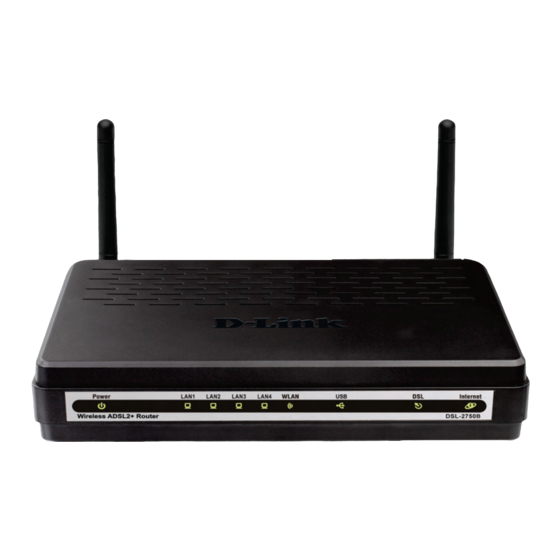
2.1 LEDs and Interfaces Front Panel The LED indicators are as follows from left to right: Power, LAN1/2/3/4, WLAN, USB, DSL, Internet. The WPS indicator is on the side panel. The following table describes the LEDs of the device. Color Status Description The power is off. - Page 7 Rear Panel Interface/Button Description RJ-11 interface that connects to the telephone set through the telephone cable. Ethernet RJ-45 interfaces that connect to the Ethernet LAN4/3/2/1 interfaces of computers or Ethernet devices. USB host port, for connecting the USB storage devices. WIRELESS Button to enable or disable WLAN.
-
Page 8: System Requirements
2.2 System Requirements Recommended system requirements are as follows: An 10 baseT/100BaseT Ethernet card is installed on your PC A hub or switch (attached to several PCs through one of Ethernet interfaces on the device) Operating system: Windows 98SE, Windows 2000, Windows ME, Windows XP, Windows Vista or Windows 7 ... -
Page 9: Standards Compatibility And Compliance
2.4 Standards Compatibility and Compliance Support application level gateway (ALG) ITU G.992.1 (G.dmt) ITU G.992.2 (G.lite) ITU G.994.1 (G.hs) ITU G.992.3 (ADSL2) ITU G.992.5 (ADSL2+) ANSI T1.413 Issue 2 IEEE 802.3 IEEE 802.3u ... -
Page 10: Connecting The Router
3.2 Connecting the Router Connect the DSL port of the router and the Modem port of the splitter with a telephone cable; connect the phone to the phone port of the splitter through a cable; and connect the incoming line to the Line port of the splitter. -
Page 11: About The Web Configuration
4 About the Web Configuration The first time you setup the Router. It is recommended that you configure the WAN connection using a single computer, to ensure that both the computer and the Router are not connected to the LAN. Once the WAN connection operates properly, you may continue to make changes to Router configuration, including IP settings and DHCP setup. -
Page 12: Logging In To The Router
4.2 Logging In to the Router The following description is a detail “How-To” user guide and is prepared for first time users. 4.2.1 First-Time Login When you log in to the DSL Router for the first time, the login wizard appears. Step 1 Open a Web browser on your computer. -
Page 13: Setup
4.3 Setup 4.3.1 Wizard Wizard enables fast and accurate configuration of Internet connection and other important parameters. The following sections describe these various configuration parameters. When subscribing to a broadband service, you should be aware of the method, by which you are connected to the Internet. Your physical WAN device can be Ethernet, DSL, or both. - Page 14 There are four steps to configure the device. Click Next to continue. Change the password for logging in to the device. The default password is admin. To secure your network, modify the password timely. Note: Confirm password must be the same as the new password. To ignore the step, click Skip.
- Page 15 Set the time and date. First NTP time server: Select the domain of the time server to which system time will be synchronized. Configure the Internet connection. Select the country and ISP. Set the VPI and VCI. If you fail to find the country and ISP from the drop-down lists, select Others.
- Page 16 If the Protocol is PPPoE or PPPoA, the page shown in either of the two figures appears. DSL-2750B User Manual...
- Page 17 Set the user name and password as provided by your ISP. DSL-2750B User Manual...
- Page 18 If the Protocol is Static IP, the page shown in the figure appears. Enter the IP Address, Subnet Mask, Default Gateway, and Primary DNS Server. If the Protocol is Dynamic IP or Bridge, the page shown in the figure appears. DSL-2750B User Manual...
- Page 19 After proper configuration, click Next. DSL-2750B User Manual...
- Page 20 Configure the wireless network, or keep the default settings. Enter the information and click Next. Enable Your Wireless Network: Enable wireless settings on LAN interface. Wireless Network Name (SSID): SSID is the name of your wireless network. All wireless-equipped devices share the same SSID to communicate with each other.
- Page 21 The page shown in the right figure appears. In this page, you can view the configuration information. You can check weather the configurations match the information provided by your ISP. DSL-2750B User Manual...
-
Page 22: Internet Setup
4.3.2 Internet Setup Choose Setup > Internet Setup. The page as shown in the right figure appears. In this page, you can configure the WAN interface of the device. DSL-2750B User Manual... - Page 23 Click Add in “INTERNET SETUP”. The page shown in the following figure appears. Description Field The virtual path between two points in an ATM network and its valid value is from 0 to 255. The virtual channel between two points in an ATM Settings network, ranging from 32 to 65535 (0 to 31 is reserved for local management of ATM traffic).
- Page 24 Click Next, the page shown in the following figure appears. DSL-2750B User Manual...
- Page 25 If you select the PPP over Ethernet (PPPoE) or PPP over ATM (PPPoA) as the connection protocol, the following page appears. PPP Username: The correct user name that your ISP provides to you. PPP Password: The correct password that your ISP provides to you. ...
- Page 26 If you select the MAC Encapsulation Routing(MER) as the connection protocol, the following page appears. Obtain an IP address automatically: The modem obtains a WAN IP address automatically and at this time it enables DHCP client functions. The WAN IP address is obtained from the uplink equipment like BAS and the uplink equipment is required to enable the DHCP server functions.
- Page 27 After proper settings, click Next. DSL-2750B User Manual...
-
Page 28: Wireless Connection
4.3.3 Wireless Connection This section includes the wireless connection setup wizard and WPS setup wizard. There are two ways to setup your wireless connection. You can use the Wireless Connection Setup Wizard or you can manually configure the connection. Choose Setup > Wireless Connection. The Wireless Connection page shown in the following figure appears. - Page 29 4.3.3.1 Wireless Wizard In Wireless Connection page, Click “Wireless Connection Setup Wizard”, the page shown in the following figure appears. If you select “Use WPA encryption instead of WEP” and “Manually assign a network key”, click “Next”, the page shown in the following figure appears. DSL-2750B User Manual...
- Page 30 If you only select “Manually assign a network key”, click “Next”, the page shown in the following figure appears. After you enter the network key, the page shown in the following figure appears, you can confirm the wireless settings in this page. Click Save to save the settings.
- Page 31 4.3.3.2 Wireless Device Add In Wireless Connection page, Click Add Wireless Device with WPS, the page shown in the following figure appears. Select Auto, click Next, the page shown in the following figure appears. When PIN is used, users are only allowed to enter no more than eight digits in the field.
- Page 32 4.3.3.3 Manual Wireless Setup If you want to configure the Internet settings of you new D-Link Router manually, click Manual Wireless Connection Setup. It will redirect to 4.4.1 Wireless Settings. 4.3.3.4 WPS Reset to Unconfigured In Wireless Connection page, Click Reset to Unconfigured, the page shown in the following figure appears.
-
Page 33: Local Network
4.3.4 Local Network You can configure the LAN IP address according to the actual application. The preset IP address is 192.168.1.1. You can use the default settings and DHCP service to manage the IP settings for the private network. The IP address of the device is the base address used for DHCP. To use the device for DHCP on your LAN, the IP address pool used for DHCP must be compatible with the IP address of the device. - Page 34 By default, Enable DHCP Server is selected for the Ethernet LAN interface of the device. DHCP service supplys IP settings to workstations configured to automatically obtain IP settings that are connected to the device through the Ethernet port. When the device is used for DHCP, it becomes the default gateway for DHCP client connected to it.
-
Page 35: Time And Date
4.3.5 Time and Date Choose Setup > Time and Date. The page shown in the following figure appears. In the Time and Date page, you can configure, update, and maintain the correct time on the internal system clock. You can set the time zone that you are in and the network time protocol (NTP) server. -
Page 36: Print Server
4.3.6 Print Server Choose Setup > Print Server. The page shown in the following figure appears. Select Enable on-board print server, the page shown in the following figure appears. Printer name: can be any text string up to 80 characters. ... -
Page 37: Advanced
4.4 Advanced This section includes advanced features used for network management, security and administrative tools to manage the device. You can view status and other information that are used to examine performance and troubleshoot. 4.4.1 Wireless Settings This function is used to modify the standard 802.11 wireless radio settings. It is recommended not to change the default settings, because incorrect settings may impair the performance of your wireless radio. - Page 38 4.4.1.1 Wireless Basics In the Wireless Settings page, click Wireless Basic, the page shown in the following figure appears. In this page, you can configure the parameters of wireless LAN clients that may connect to the device. Enable Wireless: Select this to turn Wi-Fi on and off. ...
- Page 39 4.4.1.2 Advanced Settings In the Wireless Settings page, click Advanced settings, the page shown in the following figure appears. Multicast Rate: Select the multicast transmission rate for the network. The rate of data transmission should be set depending on the speed of your wireless network.
- Page 40 Transmit Power: Adjust the transmission range here. This tool can be helpful for security purposes if you wish to limit the transmission range. WMM (Wi-Fi Multimedia): Select whether WMM is enable or disabled. Before you disable WMM, you should understand that all QoS queues or traffic classes related to wireless do not take effect.
- Page 41 4.4.1.3 MAC Filtering In the Wireless Settings page, click MAC Filtering, the page shown in the following figure appears. In this page, you can allow or deny users access the wireless router based on their MAC address. Click Add, the page shown in the following figure appears. DSL-2750B User Manual...
- Page 42 4.4.1.4 Security Settings In the Wireless Settings page, click Security Settings. The page shown in the following figure appears. Select the SSID that you want to configure from the drop-down list. Select the encryption type from the Security Mode drop-down list.You can select None, WEP, WPA-Personal and WPA-Enterprise.
- Page 43 If you select WEP, the page shown in the following figure appears. WEP (Wireless Encryption Protocol) encryption can be enabled for security and privacy. WEP encrypts the data portion of each frame transmitted from the wireless adapter using one of the predefined keys. The router offers 64 or 128 bit encryption with four keys available.
- Page 44 If you select WPA-Personal, the page shown in the following figure appears. DSL-2750B User Manual...
- Page 45 If you select WPA- Enterprise, the page shown in the following figure appears. You can only use WPA-enterprise if you have set up RADIUS server. This is the WPA/WPA2 authentication with RADIUS server instead of pre-shared key. DSL-2750B User Manual...
-
Page 46: Port Forwarding
4.4.2 Port Forwarding This function is used to open ports in your device and re-direct data through those ports to a single PC on your network (WAN-to-LAN traffic). It allows remote users to access services on your LAN, such as FTP for file transfers or SMTP and POP3 for e-mail. - Page 47 Click Add to add a virtual server. Select a service for a preset application, or enter a name in the Custom Server field. Enter an IP address in the Server IP Address field, to appoint the corresponding PC to receive forwarded packets. The Ports show the ports that you want to open on the device.
-
Page 48: Port Triggering
Click Apply to save the settings. The page shown in the following figure appears. A virtual server is added. 4.4.3 Port Triggering Some applications require that specific ports in the firewall of the device are open for the remote parties to access. Application rules dynamically open the firewall ports when an application on the LAN initiates a TCP/UDP connection to a remote party using the trigger ports. - Page 49 Click Add to add a new Port Trigger. Click the Select an application drop-down menu to choose the application you want to setup for port triggering. When you have chosen an application the default Trigger settings will populate the table below. If the application you want to setup isn’t listed, click the Custom application radio button and type in a name for the trigger in the Custom application field.
-
Page 50: Dmz
4.4.4 DMZ Since some applications are not compatible with NAT, the device supports the use of a DMZ IP address for a single host on the LAN. This IP address is not protected by NAT and it is visible to agents on the Internet with the correct type of software. - Page 51 4.4.5.1 Block Website In the Parent Control page, click Block Website. The page shown in the following figure appears. Click Add. The page shown in the following page appears. Enter the website in the URL field. Select the Schedule from drop-down list, or select Manual Schedule and select the corresponding time and days.
- Page 52 Click Apply to add the website to the BLOCK WEBSITE table.The page shown in the following figure appears. 4.4.5.2 Block MAC Address In the Parent Control page, click Block MAC Address. The page shown in the following figure appears. DSL-2750B User Manual...
- Page 53 Click Add. The page shown in the following figure appears. Enter the use name and MAC address and select the corresponding time and days. Click Apply to add the MAC address to the BLOCK MAC ADDRESS table. The page shown in the following figure appears. DSL-2750B User Manual...
-
Page 54: Filtering Options
4.4.6 Filtering Options Choose ADVANCED > Filtering Options. The Filtering Options page shown in the following figure appears. 4.4.6.1 Inbound IP Filtering In the Filtering Options page, click Inbound IP Filtering. The page shown in the following figure appears. DSL-2750B User Manual... - Page 55 Click Add to add an inbound IP filter. The page shown in the following figure appears. Enter the Filter Name and specify at least one of the following criteria: protocol, source/destination IP address, subnet mask, and source/destination port. Click Apply to save the settings. The ACTIVE INBOUND FILTER shows detailed information about each created inbound IP filter.
- Page 56 4.4.6.2 Outbound IP Filtering By default, all outgoing IP traffic from the LAN is allowed. The outbound filter allows you to create a filter rule to block outgoing IP traffic by specifying a filter name and at least one condition. In the Filtering Options page, click Outbound IP Filtering.
- Page 57 4.4.6.3 Bridge Filtering In the Filtering Options page, click Bridge Filtering. The page shown in the following figure appears. This page is used to configure bridge parameters. In this page, you can change the settings or view some information of the bridge and its attached ports.
-
Page 58: Dns
Click Add to add a bridge filter. The page shown in the following figure appears. Click Apply to save the settings. 4.4.7 DNS Domain name system (DNS) is an Internet service that translates domain names into IP addresses. Because domain names are alphabetic, they are easier to remember. -
Page 59: Dynamic Dns
4.4.8 Dynamic DNS The device supports dynamic domain name service (DDNS). The dynamic DNS service allows a dynamic public IP address to be associated with a static host name in any of the many domains, and allows access to a specified host from various locations on the Internet. -
Page 60: Storage Service
4.4.9 Storage Service Choose ADVANCED > Storage Service. The Storage Service page shown in the following figure appears. 4.4.9.1 Storage Device Info n the Storage Service page, click Storage Device Info. The page shown in the following figure appears. When you insert USB storage, this page will show the information of USB storage, such as file system, total space and used space. - Page 61 4.4.9.2 User Accounts In the Storage Service page, click Storage User Account. The page shown in the following figure appears. Click Add to add a user. The page shown in the following figure appears. Username:set valid user that access CPE’s samba server ...
-
Page 62: Multicast
4.4.10 Multicast Choose ADVANCED > Multicast. The page shown in the following figure appears. Default Version:IGMP version Query Interval(s):The query interval is the amount of time in seconds between IGMP General Query messages sent by the router (if the router is the querier on this subnet) ... -
Page 63: Network Tools
4.4.11 Network Tools Choose ADVANCED > Network Tools. The page shown in the following figure appears. DSL-2750B User Manual... - Page 64 In the NETWORK TOOLS page, you can configure port mapping, IGMP, quality of service, queue, QoS classification, UPnP, ADSL settings, SNMP, TR-069, and certificates through clicking the navigation. DSL-2750B User Manual...
- Page 65 4.4.11.1 Port Mapping Choose ADVANCED > Network Tools and click Port Mapping. The page shown in the following figure appears. In this page, you can bind the WAN interface and the LAN interface to the same group. DSL-2750B User Manual...
- Page 66 Click Add to add port mapping. The page shown in the following figure appears. The procedure for creating a mapping group is as follows: Step 1 Enter the group name. Step 2 Select the WAN interface for your new group. Step 3 Select LAN interfaces from the Available Interface list and click the <- arrow button to add them to the grouped interface list, in order to create the required mapping of the ports.
- Page 67 DSL-2750B User Manual...
- Page 68 4.4.11.2 IGMP Choose ADVANCED > Network Tools and click IGMP. The page shown in the following figure appears. When enable IGMP Snooping, the multicast data transmits through the specific LAN port which has received the request report. 4.4.11.3 Quality of Service Choose ADVANCED >...
- Page 69 4.4.11.4 Queue Config Choose ADVANCED > Network Tools and click Queue Config. The page shown in the following figure appears. Click Add. The page shown in the following figure appears. Click Save/Apply to save the settings. DSL-2750B User Manual...
- Page 70 4.4.11.5 QoS Classification Choose ADVANCED > Network Tools, and click QoS Classification, the page shown in the following figure appears.This page allows you to config various classification. DSL-2750B User Manual...
- Page 71 Click Add. The page shown in the following figure appears. DSL-2750B User Manual...
- Page 72 4.4.11.6 UPnP Choose ADVANCED > Network Tools and click UPnP. The page shown in the following figure appears. In this page, you can configure universal plug and play (UPnP). The system acts as a daemon after you enable UPnP. UPnP is used for popular audio visual software. It allows automatic discovery of your device in the network.
- Page 73 4.4.11.8 SNMP Choose ADVANCED > Network Tools and click SNMP. The page shown in the right figure appears. In this page, you can set SNMP parameters. Read Community: The network administrator must use this password to read the information of this device. ...
- Page 74 4.4.11.9 TR-069 Choose ADVANCED > Network Tools and click TR-069. The page shown in the following figure appears. In this page, you can configure the TR-069 CPE. WAN Management Protocol (TR-069) allows a Auto-Configuration Server (ACS) to perform auto-configuration, provision, collection, and diagnostics to this device.
-
Page 75: Routing
4.4.12 Routing Choose ADVANCED > Routing. The page shown in the following page appears. 4.4.12.1 Static Route Choose ADVANCED > Routing and click Static Route. The page shown in the following figure appears. This page is used to configure the routing information. In this page, you can add or delete IP routes. - Page 76 Click Add to add a static route. The page shown in the following figure appears. Destination Network Address: The destination IP address of the router. Subnet Mask: The subnet mask of the destination IP address. Use Gateway IP Address: The gateway IP address of the router. ...
- Page 77 4.4.12.3 Policy Routing Choose ADVANCED > Routing and click policy Routing. The page shown in the following figure appears. The policy route binds one WAN connection and one LAN interface. Click Add, the page shown in the following figure appears. DSL-2750B User Manual...
-
Page 78: Rip
4.4.13 Choose ADVANCED > Routing and click RIP. The page shown in the following figure appears. This page is used to select the interfaces on your device that use RIP and the version of the protocol used. If you are using this device as a RIP-enabled device to communicate with others using the routing information protocol, enable RIP and click Apply to save the settings. -
Page 79: Schedules
Click Add, the page shown in the following figure appears. In this page, please select the proper type; select the proper Use interface, and configure the other parameters in this page. After finishing setting, click Apply to save the settings. 4.4.15 Schedules Choose ADVANCED >... -
Page 80: Logout
Click Add to add schedule rule. The page shown in the following figure appears. Click Apply to save the settings. 4.4.16 Logout Choose ADVANCED > Logout. The page shown in the following figure appears. In this page, you can log out of the configuration page. DSL-2750B User Manual... -
Page 81: Maintenance
4.5 Maintenance 4.5.1 System Choose MAINTENANCE > System. The System page shown in the following figure appears. In this page, you can reboot device, back up the current settings to a file, restore the settings from the file saved previously, and restore the factory default settings. -
Page 82: Firmware Update
4.5.2 Firmware Update Choose MAINTENANCE > Firmware Update. The page shown in the following figure appears. In this page, you can upgrade the firmware of the device. The procedure for updating the firmware is as follows: Step 1 Click Browse…to search the file. Step 2 Click Update Firmware to update the configuration file. - Page 83 4.5.3.1 Account Password In the Access Controls page, click Account Password. The page shown in the following figure appears. In this page, you can change the password of the user and set time for automatic logout. You should change the default password to secure your network. Ensure that you remember the new password or write it down and keep it in a safe and separate location for future reference.
- Page 84 4.5.3.2 Services In the Access Controls page, click Services. The page shown in the following figure appears. In this page, you can enable or disable the services that are used by the remote host. For example, if telnet service is enabled and port is 23, the remote host can access the device by telnet through port 23.
-
Page 85: Diagnostics
4.5.4 Diagnostics Choose MAINTENANCE > Diagnostic. The page shown in the following figure appears. In this page, you can test the device. This page is used to test the connection to your local network, and the connection to your DSL service provider. Click Rerun Diagnostics Test to run diagnostics. -
Page 86: System Log
4.5.5 System Log Choose MAINTENANCE > System Log. The System Log page shown in the following figure appears. This page displays event log data in the chronological manner. You can read the event log from the local host or send it to a system log server. Available event severity levels are as follows: Emergency, Alert, Critical, Error, Warning, Notice, Informational and Debugging. -
Page 87: Status
4.6 Status You can view the system information and monitor performance. 4.6.1 Device Info Choose STATUS > Device Info. The page shown in the following figure appears. The page displays the summary of the device status, including the system information, Internet information, wireless information and local network information. -
Page 88: Wireless Clients
4.6.2 Wireless Clients Choose STATUS > Wireless Clients. The page shown in the following figure appears. The page displays authenticated wireless stations and their statuses. 4.6.3 DHCP Clients Choose STATUS > DHCP Clients. The page shown in the following page appears. -
Page 89: Logs
4.6.4 Logs Choose STATUS > Logs. The page shown in the following figure appears. This page lists the system log. Click Refresh to refresh the system log shown in the table. DSL-2750B User Manual... -
Page 90: Statistics
4.6.5 Statistics Choose STATUS > Statistics. The page shown in the following figure appears. This page displays the statistics of the network and data transfer. This information helps technicians to identify if the device is functioning properly. The information does not affect the function of the device. DSL-2750B User Manual... -
Page 91: Route Info
4.6.6 Route info Choose STATUS > Route Info. The page shown in the following figure appears. The table shows a list of destination routes commonly accessed by the network. 4.6.7 Logout Choose STATUS > Logout. The page shown in the following figure appears. In this page, you can log out of the configuration page. -
Page 92: Faqs
5 FAQs Question Answer Check the connection between the power adapter and the power socket. Why are all the indicators off? Check whether the power switch is turned on. Check the following: The connection between the device and the PC, the hub, or the switch. ... - Page 93 FCC Statement This equipment has been tested and found to comply with the limits for a Class B digital device, pursuant to part 15 of the FCC Rules. These limits are designed to provide reasonable protection against harmful interference in a residential installation. This equipment generates, uses and can radiate radio frequency energy and, if not installed and used in accordance with the instructions, may cause harmful interference to radio communications.