Table of Contents
Advertisement
Quick Links
Your hammer drill has been engineered and manufactured to our high standard for dependability, ease of operation, and
operator safety. When properly cared for, it will give you years of rugged, trouble-free performance.
WARNING:
this product.
Thank you for buying a RIDGID
SAVE THIS MANUAL FOR FUTURE REFERENCE
Cette perceuse a été conçue et fabriquée conformément à nos
strictes normes de fiabilité, de simplicité d'emploi et de sécurité
d'utilisation. Correctement entretenue, elle vous donnera des an-
nées de fonctionnement robuste et sans problème.
AVERTISSEMENT :
Pour réduire les risques de blessures, l'utilisateur doit
lire et veiller à bien comprendre le manuel d'utilisation
avant d'employer ce produit.
Merci d'avoir acheté un produit RIDGID
CONSERVER CE MANUEL POUR
FUTURE RÉFÉRENCE
Find Quality Products Online at:
To reduce the risk of injury, the user must read and understand the operator's manual before using
product.
®
.
®
GlobalTestSupply
www.
OPERATOR'S MANUAL
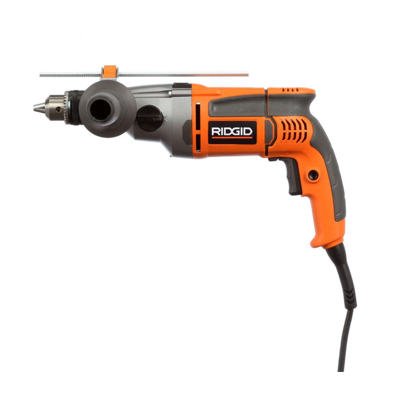
1/2 in. HAMMER DRILL
Su taladro de percusión ha sido diseñado y fabricado de conformi-
dad con nuestras estrictas normas para brindar fiabilidad, facilidad
de uso y seguridad para el operador. Con el debido cuidado, le brin-
dará muchos años de sólido funcionamiento y sin problemas.
ADVERTENCIA:
Para reducir el riesgo de lesiones, el usuario debe leer
y comprender el manual del operador antes de usar
este producto.
Le agradecemos la compra de un producto RIDGID
GUARDE ESTE MANUAL PARA
FUTURAS CONSULTAS
.com
DOUBLE INSULATED
R5011
.
®
sales@GlobalTestSupply.com
Advertisement
Table of Contents

Related Manuals for RIDGID R50111


Summary of Contents for RIDGID R50111
- Page 1 à bien comprendre le manuel d’utilisation y comprender el manual del operador antes de usar avant d’employer ce produit. este producto. Merci d’avoir acheté un produit RIDGID Le agradecemos la compra de un producto RIDGID ® ® CONSERVER CE MANUEL POUR GUARDE ESTE MANUAL PARA FUTURE RÉFÉRENCE...
-
Page 2: Table Of Contents
TABLE OF CONTENTS TABLE DES MATIÈRES / ÍNDICE DE CONTENIDO Introduction ..................................2 Introduction / Introducción General power tool safety warnings ..........................3-4 Avertissements de sécurité générales relatives aux outils électriques / advertencias de seguridad generales para la herramienta eléctrica ... -
Page 3: General Power Tool Safety Warnings
GENERAL POWER TOOL SAFETY WARNINGS Prevent unintentional starting. Ensure the switch is in WARNING the off-position before connecting to power source Read all safety warnings and all instructions. and/or battery pack, picking up or carrying the tool. Failure to follow the warnings and instructions may Carrying power tools with your finger on the switch or result in electric shock, fire and/or serious injury. -
Page 4: Avertissements De Sécurité Générales Relatives Aux Outils Électriques / Advertencias De Seguridad Generales Para La Herramienta Eléctrica Drill Safety Rules
GENERAL POWER TOOL SAFETY WARNINGS SERVICE Use the power tool, accessories and tool bits etc. in accordance with these instructions, taking into Have your power tool serviced by a qualified repair account the working conditions and the work to be person using only identical replacement parts. -
Page 5: Symbols
SYMBOLS The following signal words and meanings are intended to explain the levels of risk associated with this product. SYMBOL SIGNAL MEANING Indicates an imminently hazardous situation, which, if not avoided, will result DANGER: in death or serious injury. Indicates a potentially hazardous situation, which, if not avoided, could result WARNING: in death or serious injury. -
Page 6: Electrical
ELECTRICAL DOUBLE INSULATION EXTENSION CORDS Double insulation is a concept in safety in electric power When using a power tool at a considerable distance from tools, which eliminates the need for the usual three-wire a power source, be sure to use an extension cord that has grounded power cord. -
Page 7: Features
FEATURES PRODUCT SPECIFICATIONS Input .........120 V, 60 Hz, AC only, 8.5 Amps No Load Speed ......Low (0-1,000 r/min. (RPM) Hammer Speed ......0-19,000/0-57,000 BPM High (0-3,000 r/min. (RPM) KNOW YOUR HAMMER DRILL DEPTH STOP ROD See Figure 1, page 14. A depth stop rod has been supplied with this product to The safe use of this product requires an understanding of assist in controlling the depth of drilled holes. -
Page 8: Assembly
ASSEMBLY UNPACKING WARNING: This product requires assembly. Do not attempt to modify this tool or create Carefully remove the tool and any accessories from the accessories not recommended for use with this box. Make sure that all items listed in the packing list are tool. -
Page 9: Operation
OPERATION WARNING: NOTICE: Do not allow familiarity with tools to make you To prevent gear damage, always allow the chuck careless. Remember that a careless fraction of a to come to a complete stop before changing the second is sufficient to inflict severe injury. direction of rotation. - Page 10 OPERATION NOTE: The hammer drill has not been designed for reverse Insert the drill bit. hammering. Tighten the chuck jaws securely on the drill bit, using the Use carbide-tipped bits and select hammer mode when chuck key provided. drilling in hard materials such as brick, tile, concrete, etc.
- Page 11 OPERATION WOOD AND METAL DRILLING Check the direction of rotation selector for the correct setting (forward or reverse). For maximum performance, use high speed steel bits for Secure the material to be drilled in a vise or with clamps wood or metal drilling. Select drilling mode. Begin drilling to keep it from turning as the drill bit rotates. at a very low speed to prevent the bit from slipping off the ...
-
Page 12: Maintenance
MAINTENANCE CHUCK REMOVAL WARNING: See Figures 14 - 16, page 16. When servicing use only identical RIDGID The chuck may be removed and replaced with a new one. replacement parts. Use of any other parts may Unplug the drill. -
Page 13: Entretien / Mantenimiento Warranty
Fig. 1 Fig. 4 A - Lock-on button (bouton de verrouillage, botón del seguro de encendido) B - Switch trigger (gâchette, gatillo del interruptor) Fig. 5 A - Drilling/hammer mode selector (sélecteur basse], engranaje de dos velocidades de perceuse / marteau, selector de taladro / [alta-baja]) percusión) H - Auxiliary handle assembly (poignée auxiliaire,... -
Page 14: Garantie / Garantía Figure Numbers (Illustrations)
Fig. 6 Fig. 9 Fig. 11 A - Two-speed gear shift knob (train d’engrenages Fig. 12 à deux vitesses, engranaje de dos velocidades) B - Lo (1) (basse [1], velocidad baja [1]) A - To increase drilling depth (pour augmenter la C - Hi (2) (haute [2], velocidad alta [2]) profondeur de perçage, para aumentar la profundidad de taladrado) - Page 15 Fig. 14 Fig. 15 Fig. 16 A - Screwdriver (tournevis, destornillador) A - Mallet (maillet, mazo de goma) B - Chuck jaws (mors du mandrin, mordazas del portabrocas) A - Mallet (maillet, mazo de goma) C - Hex key (clé hexagonale, llave hexagonal) B - Hex key (clé...