Table of Contents
Advertisement
Quick Links
Advertisement
Table of Contents

Related Manuals for Bard WL372


Summary of Contents for Bard WL372
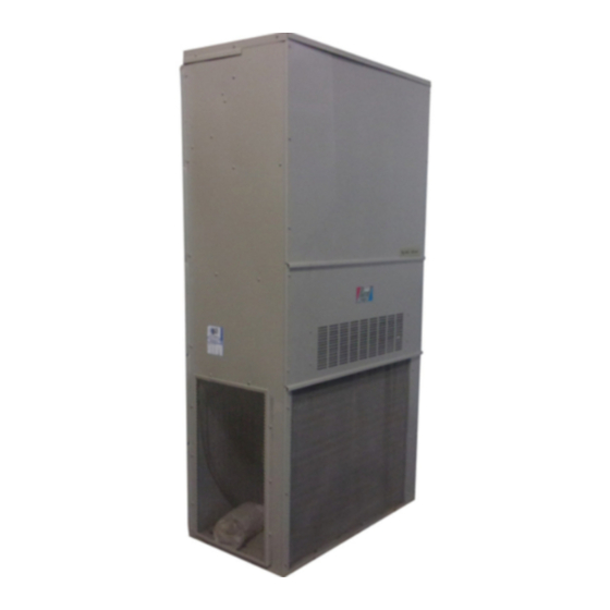
- Page 1 WALL MOUNTED PACKAGED AIR CONDITIONER INSTALLATION INSTRUCTIONS WL302 Model: WL372 Manual No.: 2100-405A Bard Manufacturing Company, Inc. Supersedes: 2100-405 Bryan, Ohio 43506 File: Volume III, Tab 16 Since 1914...Moving ahead, just as planned. Date: 07-25-06 Manual 2100-405A Page 1 of 18...
-
Page 2: Table Of Contents
CONTENTS Getting Other Information and Publications Start Up For more information, Important Installer Note ......... 15 contact these publishers ......... 3 High Pressure Switch ........... 15 Three Phase Scroll Compressor Start Up Info ..15 Wall Mount General Information Phase Monitor ............15 Air Conditioner Wall Mount Model Nomenclature ... -
Page 3: Getting Other Information And Publications
Getting Other Information and Publications FOR MORE INFORMATION, CONTACT These publications can help you install the air THESE PUBLISHERS: conditioner or heat pump. You can usually find these at your local library or purchase them directly from the publisher. Be sure to consult current edition of each ACCA Air Conditioning Contractors of America standard. -
Page 4: Wall Mount General Information
WALL MOUNT GENERAL INFORMATION AIR CONDITIONER WALL MOUNT MODEL NOMENCLATURE — MODEL NUMBER REVISIONS CONTROL MODULES COLOR OPTIONS J - Standard On All Models X - Beige (Standard) VOLTS & PHASE 1 - White CAPACITY A - 230/208/60/1 2 - Mesa Tan COIL OPTIONS 24 - 2 Ton B - 230/208/60/3... -
Page 5: Figure 1 Unit Dimensions
Manual 2100-405A Page 5 of 18... -
Page 6: Shipping Damage
TABLE 3 ELECTRIC HEAT TABLE SHIPPING DAMAGE Size of unit for a proposed installation should be based on heat loss calculation made according to methods of Upon receipt of equipment, the carton should be checked Air Conditioning Contractors of America (ACCA). The for external signs of shipping damage. -
Page 7: Filters
Any grille that meets the 5/8 inch louver criteria, may be used. It is recommended that Bard Return Air Grille Kit CONDENSATE DRAIN RG-2 through RG-5 or RFG-2 through RFG-5 be A plastic drain hose extends from the drain pan at the installed when no return duct is used. -
Page 8: Installation Instructions
INSTALLATION INSTRUCTIONS WALL MOUNTING INFORMATION 7. Secure rain flashing to wall and caulk across entire length of top. See Figure 3. 1. Two holes, for the supply and return air openings, 8. For additional mounting rigidity, the return air and must be cut through the wall as shown in Figure 3. -
Page 9: Wiring - Low Voltage Wiring
WIRING – LOW VOLTAGE WIRING Five (5) wires should be run from thermostat subbase to the 24V terminal board in the unit. A five conductor, 18 230/208V, 1 phase and 3 phase equipment dual primary gauge copper, color-coded thermostat cable is voltage transformers. -
Page 10: Figure 3 Mounting Instructions
Manual 2100-405A Page 10 of 18... -
Page 11: Figure 4 Wall-Mounting Instructions
FIGURE 4 WALL MOUNTING INSTRUCTIONS SEE FIGURE 3 – MOUNTING INSTRUCTIONS FOR OPENING SIZES FIGURE 5 WALL MOUNTING INSTRUCTIONS SEE UNIT DIMENSIONS FIGURE 1 FOR ACTUAL DIMENSIONS Manual 2100-405A Page 11 of 18... -
Page 12: Figure 6 Common Wall-Mounting Installations
FIGURE 6 COMMON WALL MOUNTING INSTALLATIONS Manual 2100-405A Page 12 of 18... -
Page 13: Figure 7 Electric Heat Clearances
FIGURE 7 ELECTRIC HEAT CLEARANCE Side section view of supply air duct for wall mounted unit showing 1/4 inch clearance to combustible surfaces. WARNING • A minimum of 1/4 inch clearance must be maintained between the supply air duct and combustible materials. This is required for the first 3 feet of ducting. -
Page 14: Figure 8 Low Voltage Wiring
FIGURE 8 LOW VOLTAGE WIRING Manual 2100-405A Page 14 of 18... -
Page 15: Start Up
The phase monitor in this unit is equipped with two LEDs. If the Y signal is present at the phase monitor The WL372 models are supplied with a remote reset and phases are correct the green LED will light. high pressure switch. If tripped, this pressure switch... -
Page 16: Compressor Control Module
COMPRESSOR CONTROL MODULE Alarm Relay Output The compressor control module is optional on the Alarm terminal is output connection for applications models covered by this manual. The compressor control where alarm relay is employed. This terminal is is an anti-short cycle/lockout timer with high and low powered whenever compressor is locked out due to HPC pressure switch monitoring and alarm relay output. -
Page 17: Figure 9 Fan Blade Setting
TROUBLESHOOTING FAN BLADE SETTING DIMENSIONS The suction line temperatures in Table 8 are based upon 80ºF dry bulb/67ºF wet bulb (50 percent R.H.) Shown in the drawing below is the correct fan blade temperature and rated airflow across the evaporator setting dimension for proper air delivery across the during cooling cycle. -
Page 18: Cooling Pressure Table
TABLE 12 COOLING PRESSURE – OUTDOOR TEMPERATURE °F Low side pressure ± 2 psig High side pressure ± 5 psig Tables are based upon rated CFM (airflow) across the evaporator coil and should be found under section titled "refrigerant charge" elsewhere in manual. If there is any doubt as to correct charge being in the system, the charge should be removed, system evacuated and recharged to serial plate instructions.