Advertisement
Quick Links
SERVICE MANUAL
01
2003
49774
1
Important Safety Precautions . . . . . . . . . . . . . . . . . . . . . . . . . . . . . . . . . . . . . . . . . . . . . . . . . . . . . . . . . . . 1-2
2
Disassembly method . . . . . . . . . . . . . . . . . . . . . . . . . . . . . . . . . . . . . . . . . . . . . . . . . . . . . . . . . . . . . . . . . . 1-3
3
Adjustment method. . . . . . . . . . . . . . . . . . . . . . . . . . . . . . . . . . . . . . . . . . . . . . . . . . . . . . . . . . . . . . . . . . . 1-12
4
Description of major ICs . . . . . . . . . . . . . . . . . . . . . . . . . . . . . . . . . . . . . . . . . . . . . . . . . . . . . . . . . . . . . . . 1-16
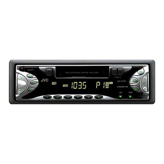
CASSETTE RECEIVER
KS-F171
S.BASS
SEL
DISP
TABLE OF CONTENTS
COPYRIGHT © 2003 VICTOR COMPANY OF JAPAN, LTD.
KS-F171
Area Suffix
U ------- Other Areas
No.49774
2003/01
Advertisement

Related Manuals for JVC KS-F171


Summary of Contents for JVC KS-F171
- Page 1 KS-F171 SERVICE MANUAL CASSETTE RECEIVER 49774 2003 KS-F171 Area Suffix U ------- Other Areas S.BASS DISP TABLE OF CONTENTS Important Safety Precautions ............1-2 Disassembly method .
- Page 2 KS-F171 SECTION 1 Important Safety Precautions 1.1 Safety Precautions Burrs formed during molding may be left over on some parts of the chassis. Therefore, pay attention to such burrs in the case of preforming repair of this system. 1-2 (No.49774)
- Page 3 KS-F171 SECTION 2 Disassembly method 2.1 Main body 2.1.1 Removing the front panel assembly (See Fig.1) (1) Press the release button and remove the front panel as- Front panel assembly sembly. Release button Fig.1 2.1.2 Removing the bottom cover (See Fig.2) •...
- Page 4 KS-F171 2.1.4 Removing the heat sink (See Fig.4) • Prior to performing the following procedure, remove the front panel assembly. (1) Remove the two screws B and two screws C attaching the heat sink on the left side of the body, and remove the heat sink.
- Page 5 KS-F171 2.1.7 Removing the cassette mechanism assembly (See Fig.7) • Prior to performing the following procedure, remove the front Cassette mechanism assembly panel assembly, bottom cover, front chassis, heat sink, rear panel and main board. (1) Remove the four screws H attaching the cassette mecha- nism assembly from the top chassis.
- Page 6 KS-F171 2.1.9 Removing the relay board (See Fig.9) • Prior to performing the following procedure, remove the front Relay board CP722 panel assembly, bottom cover, front chassis, heat sink, rear panel, main board and cassette mechanism assembly. (1) Disconnect the wire from CP722 on the relay board.
- Page 7 KS-F171 2.1.11 Removing the switch (LCD & key) board (See Fig.11~13) • Prior to performing the following procedure, remove the front panel assembly. (1) Remove the four screws M attaching the rear cover on the back of the front panel assembly.
- Page 8 KS-F171 2.2 Cassette mechanism assembly • Prior to performing the following procedures, remove the head 2.2.4 Removing the playback head amplifier board, the relay board and the mechanism bracket. (See Fig.2) • Prior to performing the following procedure, remove the direc- 2.2.1 Removing the direction switch board...
- Page 9 KS-F171 2.2.6 Removing the cassette hanger / cassette holder Cassette holder (See Fig.3) Return link Joint i • Prior to performing the following procedure, remove the FF / Cassette hanger REW lever assembly. Eject lever (1) From the rear of the unit, bend the two tabs f outwards and disengage the two joints g in the direction of the arrow.
- Page 10 KS-F171 2.2.9 Removing the Flywheel (BF) and (BR) assembly 2.2.10 Removing the reel base assembly (See Fig.4 and 5) (See Fig.5 and 6) • Prior to performing the following procedure, remove the cas- (1) Raise the part k of the reel base assembly slightly and re- sette hanger / cassette holder.
- Page 11 KS-F171 2.2.11 Removing the mute switch board Cassette mechanism assembly (See Fig.8) Rower switch (1) Unsolder the two wires l on the mute switch board on the Soldering l Motor assembly back of the cassette mechanism assembly. (2) Remove the screw H attaching the mute switch board.
- Page 12 KS-F171 SECTION 3 Adjustment method Test Instruments reqired for adjustment Standard volume position 1. Digital oscilloscoe(100MHz) Balance and Bass, Treble volume, Fader 2.Frequency counter meter :Center(Indication"0") 3.Electric voltmeter Loudness,Dolby NR,Sound,Cruise:Off 4.Wow & flutter meter Volume position is about 2V at speaker output with 5.Test tapes...
- Page 13 KS-F171 Information for using a car audio service jig 1. For 1995 and 1996, we're advancing efforts to make our extension cords common for all car audio products. Please use this type of extension cord as follows. 2. As a U-shape type top cover is employed, this type of extension cord is needed to check operation of the mechanism assembly after disassembly.
- Page 14 KS-F171 Arrangement of adjusting & test points Cassette mechanism (Surface) Motor assembly Tape speed adjust Playback head Azimuth screw Head section view Head azimuth screw Fixed screw Playback head Height adjusting screw Height adjusting screw Height adjusting screw 1-14 (No.49774)
- Page 15 KS-F171 Mechanism adjustment section Item Adjusting & Confirmation Methods Adjust Std. Value 1. Head azimuth "Head Height Adjustment" Note Adjust the azimuth directly. When you adjust the height A Line using a mirror tape, remove the cassette housing from the mechanism chassis.
- Page 16 KS-F171 SECTION 4 Description of major ICs 4.1 LC75823W (IC651) : LCD driver • Pin Layout & Symbol 64 63 62 61 60 59 58 57 56 55 54 53 52 51 50 49 17 18 19 20 21 22 23 24 25 26 27 28 29 30 31 32 •...
- Page 17 KS-F171 4.2 LC72362N-9B39 (IC701) : Micon • Pin layout 24 - 1 41 - 64 • Pin functions Symbol Function Symbol Function - Non connect I Crystal oscillator - Non connect - To GND - Non connect J BUS SI...
- Page 18 KS-F171 4.3 LC75421M-X (IC931): E. volume • Pin layout • Block diagram 1-18 (No.49774)
- Page 19 KS-F171 • Pin functions Pin No Symbol Function Serial data input terminal for control Chip enable terminal LROUT Rear Lch fader output terminal LFOUT Front Lch fader output terminal LFIN Front Lch input terminal LOUT C & R connection terminal for super bass band C &...
- Page 20 KS-F171 4.4 LA4743K (IC981) : Power amp. • Block diagram 2200 F 0.022 F Vcc 1/2 Vcc 3/4 IN 1 OUT 1+ 0.22 F OUT 1- PWR GND1 Protective circuit OUT 2+ IN 2 OUT 2- 0.22 F PWR GND2...
- Page 21 KS-F171 • Terminal layout • Pin function Pin No. Symbol Function Header of IC Power GND Outpur(-) for front Rch STDBY Stand by input Output (+) for front Rch Power input Output (-) for rear Rch Power GND Output (+) for rear Rch...
- Page 22 KS-F171 4.5 AN80T05LF (IC781) : Regulator • Pin layout & Block diagram Reference Voltage ASO & Peak Current Protection Thermal Protection Drive Drive Drive Drive Drive MODE2 MODE1 5.6V 8.7V 8.7V 8.7V • Pin function Pin No. Symbol Function 10V power supply for illumination.
- Page 23 KS-F171 (No.49774)1-23...
- Page 24 KS-F171 VICTOR COMPANY OF JAPAN, LIMITED AV & MULTIMEDIA COMPANY 10-1,1chome,Ohwatari-machi,Maebashi-city,371-8543,Japan (No.49774) Printed in Japan 200301WPC...