Table of Contents
Advertisement
Quick Links
Advertisement
Table of Contents

Related Manuals for Broan InVent 80 CFM Series


Summary of Contents for Broan InVent 80 CFM Series
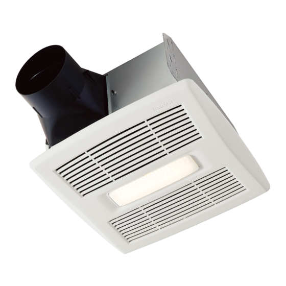
- Page 1 Ventilador/Lámpara con sensor de humedad Model numbers: AE80SL Números de modelo: AE110SL INSTALLATION AND USE & CARE INSTRUCTIONS INSTRUCCIONES PARA INSTALACIÓN, USO Y CUIDADO English - See page 2 Español - Consulte la página 9 © 2016 Broan-NuTone LLC 99045716A...
- Page 2 Please visit our website - www.broan.com to register this product and to view installation tips and videos. Installer: Leave this manual with the homeowner. READ AND SAVE THESE INSTRUCTIONS WARNING CAUTION To reduce the risk of fire, electric • For general ventilating use only. Do not...
-
Page 3: Cleaning And Maintenance
80%. If fan is still responding too often at feature. For odor or vapor control, the fan can be 80%, contact Broan Technical Support. energized by cycling the power switch. Once the fan has been energized in this manner, it will remain on To adjust the %HUMIDITY: for the set timer period. -
Page 4: All Installations
ALL INSTALLATIONS Start here. 1. Remove blower and all packing material from fan WARNING housing. • Disconnect the electrical power supply and lock out the service panel. COOKING AREA Do not install above or inside this area. NOT FOR USE IN Cooking A COOKING AREA. -
Page 5: New Construction
NEW CONSTRUCTION 5. Connect 4-in. round duct. For Retrofit Installation - Skip to Page 6. 3. Attach damper/duct connector to fan housing. Push connector through opening from inside of housing. Engage tabs and secure with screw from parts bag. 6. Connect wiring. Bend tab to expose desired access hole. - Page 6 7. Install blower. Push grille up against ceiling. Re-install blower. Secure blower with 2 screws from parts bag and plug blower into black receptacle. Plug in humidity- sensing control. CAUTION • Make sure that the wiring inside of the housing does not interfere with re-installation of the blower.
- Page 7 5. Connect wiring. 7. Connect 4-in. round duct. Bend tab to expose desired access hole. Connect Pull existing ducting through housing discharge power cable to housing with appropriate UL approved opening. connector. Connect wires per diagram on page 8. Re- install wiring panel and secure with screw from parts Attach and tape ducting to duct connector.
-
Page 8: Wiring Diagrams
WIRING DIAGRAMS WIRING OPTION #1 WIRING OPTION #2 • When first switch (1) is ON, fan will operate auto- • When first switch (1) is ON, fan will operate auto- matically, based on room humidity conditions. matically based on room humidity conditions. •...