Table of Contents
Advertisement
Available languages
Available languages
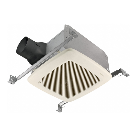
HUMIDITY SENSING FAN
To register this product visit: www.broan.com
READ AND SAVE THESE INSTRUCTIONS
WARNING
TO REDUCE THE RISK OF FIRE, ELECTRIC SHOCK, OR IN-
JURY TO PERSONS, OBSERVE THE FOLLOWING:
1. Use this unit only in the manner intended by the manufacturer.
If you have questions, contact the manufacturer at the address
or telephone number listed in the warranty.
2. Before servicing or cleaning unit, switch power off at service
panel and lock the service disconnecting means to prevent
power from being switched on accidentally. When the service
disconnecting means cannot be locked, securely fasten a
prominent warning device, such as a tag, to the service panel.
3. Installation work and electrical wiring must be done by a qualified
person(s) in accordance with all applicable codes and standards,
including fire-rated construction codes and standards.
4. Sufficient air is needed for proper combustion and exhausting
of gases through the flue (chimney) of fuel burning equipment
to prevent backdrafting. Follow the heating equipment manufac-
turer's guideline and safety standards such as those published
by the National Fire Protection Association (NFPA), and the
American Society for Heating, Refrigeration and Air Condition-
ing Engineers (ASHRAE), and the local code authorities.
5. When cutting or drilling into wall or ceiling, do not damage
electrical wiring and other hidden utilities.
6. Ducted fans must always be vented to the outdoors.
7. Acceptable for use over a tub or shower when connected to a
GFCI (Ground Fault Circuit Interrupter) - protected branch circuit.
8. This unit must be grounded.
CAUTION
1. For general ventilating use only. Do not use to exhaust hazard-
ous or explosive materials and vapors.
2. This product is designed for installation in flat ceilings only. DO
NOT MOUNT THIS PRODUCT IN A WALL.
3. To avoid motor bearing damage and noisy and/or unbalanced
impellers, keep drywall spray, construction dust, etc. off power
unit.
4. Please read specification label on product for further information
and requirements.
Installer: Leave this manual with the homeowner.
OPERATION
The humidity control and fan can be operated separately. Use a
1- or 2-function wall control. Do not use a dimmer switch to operate
the humidity control. See "Connect Wiring" for details.
SENSOR OPERATION
The humidity-sensing fan uses a sophisticated humidity sensor
that responds to: (a) rapid to moderate increases in humidity or (b)
humidity above a set-point. The humidity sensor may occasionally
turn the fan ON when environmental conditions change.
MANUAL ON WITH TIMED OFF
The humidity sensing fan has an additional operation feature. For
odor or vapor control, the fan can be energized by cycling the
power switch. Once the fan has been energized in this manner, it
will remain on for 20 minutes.
To manually energize the fan:
1. If fan power switch is already ON, proceed to Step 2; otherwise,
turn power switch ON for more than 1 second.
2. Turn fan power switch OFF for less than 1 second.
3. Turn fan power switch back ON and fan will turn ON.
CLEANING & MAINTENANCE
For quiet and efficient operation, long life, and attractive appear-
ance - lower or remove grille and vacuum interior of unit with the
dusting brush attachment.
The motor is permanently lubricated and never needs oiling. If the
motor bearings are making excessive or unusual noises, replace
the motor / blower wheel assembly.
SENSOR CLEANING
The humidity sensor is mounted in the control housing. The sensor
will operate most reliably when cleaned occasionally as follows:
1. Disconnect power at service entrance.
2. Remove the grille. Use a dry dustcloth, clean toothbrush,
or lightly vacuum to clean sensor and grille. DO NOT USE
ABRASIVE CLOTH, STEEL WOOL PADS, OR SCOURING
POWDERS.
3. DO NOT USE cleaning sprays, solvents, or water on or near
the sensor!
MODEL QTRE100S
Page 1
Advertisement
Table of Contents

Related Manuals for Broan QTRE100S


Summary of Contents for Broan QTRE100S
- Page 1 MODEL QTRE100S Page 1 HUMIDITY SENSING FAN To register this product visit: www.broan.com READ AND SAVE THESE INSTRUCTIONS WARNING OPERATION TO REDUCE THE RISK OF FIRE, ELECTRIC SHOCK, OR IN- The humidity control and fan can be operated separately. Use a JURY TO PERSONS, OBSERVE THE FOLLOWING: 1- or 2-function wall control.
-
Page 2: Typical Installations
MODEL QTRE100S Page 2 TYPICAL INSTALLATIONS • Locate unit above (GFCI protected circuit required) or within 5 feet of shower head. • Locate unit away from heating or cooling sources which can affect humidity levels. • Do not locate near window. Unit may respond to the outdoor humidity level. • Unit must be installed in ceiling to properly sense moisture. • Locate unit only on flat ceilings up to 12 feet high for proper sensing. • The fan will operate most efficiently when located where the shortest possible duct run and minimum number of elbows will be needed. -
Page 3: Connect Wiring
MODEL QTRE100S Page 3 1b. Mount housing anywhere between 2. Attach damper/ trusses, joists, or I-joists using hanger duct connector. bars. Snap damper / duct con- nector onto housing. Make sure connector is flush Sliding hanger bars are provided to allow for accurate posi- with top of housing and tioning of housing anywhere between framing. -
Page 4: Service Parts
99420665 Thumbscrew, #8-18 x .375 To qualify for warranty service, you must (a) notify Broan at the address or tele- phone number stated below, (b) give the model number and part identification and Order service parts by “Part No.” - not by “Key No.”... -
Page 5: Operación
MODELO QTRE100S Página 5 VENTILADOR CON SENSOR DE HUMEDAD Para registrar este producto, visite: www.broan.com LEA Y CONSERVE ESTAS INSTRUCCIONES ADVERTENCIA OPERACIÓN PARA REDUCIR EL RIESGO DE INCENDIOS, DESCARGAS El control de humedad y el ventilador pueden funcionar sepa- ELÉCTRICAS O LESIONES PERSONALES, OBSERVE LAS radamente. -
Page 6: Instalaciones Típicas
MODELO QTRE100S Página 6 INSTALACIONES TÍPICAS • C oloque la unidad sobre o dentro de una distancia de 1.5 m (5 pies) de la cabeza de la regadera (se requiere un circuito protegido con un GFCI). • U bique la unidad lejos de fuentes de calefacción o en- friamiento que puedan afectar los niveles de humedad. -
Page 7: Conexión Eléctrica
MODELO QTRE100S Página 7 1b. Instale la cubierta en cualquier parte 2. Acople el conectador entre las armaduras, viguetas o viguetas del regulador de tiro/ “I” por medio de barras de suspensión. conducto. Conecte a presión el Se proporcionan barras de suspensión deslizantes para facilitar conectador del regulador de la colocación adecuada de la cubierta en cualquier parte entre la... -
Page 8: Piezas De Repuesto
Tornillo de mariposa n.º 8-18 x 0.375 las garantías anteriores. Para tener derecho al servicio de la garantía, usted debe (a) notificar a Broan a la Al hacer el pedido de una pieza de servicio se debe especificar dirección y número de teléfono que aparecen abajo, (b) proporcionar el número de modelo y la identificación de la pieza y (c) describir la naturaleza de cualquier...