Table of Contents
Advertisement
Quick Links
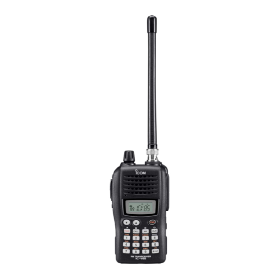
INSTRUCTION MANUAL
FM TRANSCEIVER
iV85
iV85E
iV85-T
This device complies with Part 15 of the FCC Rules. Operation is
subject to the following two conditions: (1) this device may not cause
harmful interference, and (2) this device must accept any interference
received, including interference that may cause undesired operation.
Advertisement
Table of Contents

Related Manuals for Icom IC-iV85


Summary of Contents for Icom IC-iV85
- Page 1 INSTRUCTION MANUAL FM TRANSCEIVER iV85 iV85E iV85-T This device complies with Part 15 of the FCC Rules. Operation is subject to the following two conditions: (1) this device may not cause harmful interference, and (2) this device must accept any interference received, including interference that may cause undesired operation.
-
Page 2: Foreword
FOREWORD IMPORTANT READ ALL INSTRUCTIONS Thank you for purchasing this Icom transceiver. The IC-V85 carefully and completely is designed and built with Icom’s superior before using the transceiver. FM TRANSCEIVER technology and craftsmanship. With proper care, this trans- SAVE THIS INSTRUCTION MANUAL—... -
Page 3: Precautions
PRECAUTIONS RWARNING RF EXPOSURE! RWARNING! NEVER This device emits connect the transceiver to an AC Radio Frequency (RF) energy. Extreme caution should be ob- outlet. This may pose a fire hazard or result in an electric shock. served when operating this device. If you have any questions NEVER connect a power supply of more than 16 V DC regarding RF exposure and safety standards please refer to... -
Page 4: Supplied Accessories
(Li-Ion: BP-227) or installed batteries will be- come exhausted. For USA only: Caution: Changes or modifications to this transceiver, not ex- pressly approved by Icom Inc., could void your authority to operate this transceiver under FCC regulations. -
Page 5: Option List
OPTION LIST • BP-226 • HM-75A/HM-131L/HM-158L BATTERY CASE SPEAKER MICROPHONES Battery case for 5 × AA (LR6) size alkaline batteries. Combination speaker-microphones that provide convenient operation while hanging the transceiver from your belt. • BP-227 ION BATTERY PACK HM-75A has 4 function switches for remote control capabilities. 7.2 V/1700 mAh Lithium-Ion battery pack. -
Page 6: Table Of Contents
TABLE OF CONTENTS FOREWORD ................ i 4 BASIC OPERATION..........17–21 ■ Power ON..............17 IMPORTANT................. i ■ VFO mode selection..........17 EXPLICIT DEFINITIONS............i ■ Setting a frequency ........... 17 PRECAUTIONS .............. ii–iii ■ Setting audio/squelch level ........19 SUPPLIED ACCESSORIES ..........iii ■... - Page 7 ■ Memory bank selection ..........30 11 SET MODES............47–56 ■ Memory bank setting..........30 ■ SET MODE ............... 47 ■ Transferring bank contents........31 ■ INITIAL SET MODE ..........51 7 DTMF MEMORY............. 32–34 12 SET MODE INSPECTION ........57–58 ■...
-
Page 8: Quick Reference Guide
QUICK REFERENCE GUIDE ■ Preparation D Antenna D Battery pack replacement Attach the antenna to the transceiver Before replacing the battery pack, push and hold [PWR] for 1 as illustrated at right. sec. to turn the power OFF. • To attach the battery pack Slide the battery pack on the back of the transceiver in the di- rection of the arrow (q), then lock it with the battery release button. - Page 9 QUICK REFERENCE GUIDE D Battery case— optional for some versions BP-226 Latch Fig.1 When using a BP-226 attached to the trans- BATTERY CASE ceiver, install 5 AA (LR6) size alkaline batteries as illustrated at right. q Hook your finger under the latch, and open the cover in the direction of the arrow (q).
- Page 10 QUICK REFERENCE GUIDE D D Regular charging When using a BP-227 attached to the trans- BATTERY PACK ceiver, prior to using the transceiver for the first time, the bat- Transceiver tery pack must be fully charged for optimum life and operation.
-
Page 11: Your First Contact
QUICK REFERENCE GUIDE ■ Your first contact 2. Adjusting audio output level Now that you have your IC-V85 ready, you are excited to get on the air. We would like to walk you through a few basic op- ➥ Rotate [VOL] to set the desired [VOL] erational steps to make your first “On The Air”... -
Page 12: Repeater Operation
QUICK REFERENCE GUIDE ■ Repeater operation Direct frequency input from the keypad is also available. 1. Setting duplex ➥ To enter the desired frequency, ➥ Push [FUNC], then [ ](4) sev- enter 6 digits starting from the eral times to select minus duplex 100 MHz digit. -
Page 13: Programming Memory Channels
QUICK REFERENCE GUIDE ■ Programming memory channels The IC-V85 has a total of 107 memory channels (including 6 3. Writing a memory channel ➥ Push [FUNC], then push and hold scan edges and 1 call channel) for storing often used operat- ing frequency, repeater settings, etc. -
Page 14: Accessories
ACCESSORIES ■ Accessory attachment D Antenna Attach the antenna to the transceiver as illustrated below. Keep the [SP/MIC] cap (SP/MIC jack cover) attached when jacks are not in use to keep the contacts clean. Attach the [SP/MIC] cap. [SP/MIC] cap... - Page 15 ACCESSORIES D Belt clip D Hand strap Slide the hand strap through the loop on the top of the rear panel Conveniently attaches to your belt. as illustrated below. Facilitates carrying. Attach the belt clip with the supplied screws using a phillips screwdriver.
-
Page 16: Panel Description
PANEL DESCRIPTION ■ Switches, controls, keys and connectors CONTROL DIAL ANTENNA CONNECTOR Speaker PTT SWITCH EXTERNAL SPEAKER/ Microphone MICROPHONE JACKS FUNCTION DISPLAY SQUELCH/MONITOR SWITCH UP/DOWN KEYS POWER KEY EXTERNAL DC JACK KEYPAD... - Page 17 PANEL DESCRIPTION q CONTROL DIAL [VOL] (p. 19) y EXTERNAL DC JACK [DC 11V] ➥ Connect an external DC power supply through the op- Rotate to adjust the volume level. tional CP-19R for external DC operation. (p. 16) The assigned function for [VOL] and [Y Y ]/[Z Z ] can be ex- ➥...
- Page 18 PANEL DESCRIPTION D Keypad [1• TONE ➥ Input digit “1” during frequency input, memory channel selection, etc. (pgs. 17, 26) ➥ After pushing [FUNC], selects the subaudible tone function. (pgs. 22, 39) [2• BEEP ➥ Input digit “2” during frequency input, memory channel selection, etc.
- Page 19 PANEL DESCRIPTION [6• [0• SKIP ➥ Input digit “6” during frequency input, memory ➥ Input digit “0” during frequency input, memory channel selection, etc. (pgs. 17, 26) channel selection, etc. (pgs. 17, 26) ➥ After pushing [FUNC], sets and cancels skip ➥...
-
Page 20: Function Display
PANEL DESCRIPTION ■ Function display q BUSY INDICATOR e TRANSMIT INDICATOR (p. 19) ➥ Appears when a signal is being received or the squelch Appears during transmit. is open. r PAGER CALL INDICATOR (p. 46) ➥ Blinks while the monitor function is activated. (p. 19) Blinks when a pager call is received. - Page 21 PANEL DESCRIPTION y TONE INDICATOR !3 MEMORY MODE INDICATOR (p. 26) ➥ “ ” appears while the subaudible tone encoder is in Appears while in memory mode or channel number indica- use. (p. 23) tion mode. ➥ “ ” appears while the tone (CTCSS) squelch function !4 SKIP CHANNEL INDICATOR (p.
-
Page 22: Battery Packs
BATTERY PACKS ■ Battery pack replacement D D Battery packs q Before replacing the battery pack, push and hold [PWR] Battery for 1 sec. to turn the power Voltage Capacity Battery life* pack OFF. Battery case for AA —* BP-226 (LR6)×5 alkaline 7.2 V 1700 mAh... - Page 23 BATTERY PACKS D Battery case— optional for some versions BP-226 Latch Fig.1 When using a BP-226 attached to the trans- BATTERY CASE ceiver, install 5 AA (LR6) size alkaline batteries as illustrated at right. q Hook your finger under the latch, and open the cover in the direction of the arrow (q).
-
Page 24: Cautions
• R DANGER! NEVER incinerate an used battery pack since internal battery gas may cause it to rupture, or may cause • R DANGER! Use and charge only specified Icom battery an explosion. packs with Icom radios. Only Icom battery packs are tested •... - Page 25 • CAUTION! DO NOT charge the battery outside of the spec- ified temperature range: 10˚C to +40˚C (+50˚F to +104˚F). Icom recommends charging the battery at +20˚C (+68˚F). The battery may heat up or rupture if charged out of the specified temperature range.
-
Page 26: Regular Charging
BATTERY PACKS ■ Regular charging When using a BP-227 attached to the trans- BATTERY PACK Transceiver ceiver, prior to using the transceiver for the first time, the bat- tery pack must be fully charged for optimum life and operation. • BC-167A/D D D Charging note •... -
Page 27: Rapid Charging
BATTERY PACKS ■ Rapid charging D AD-100 installation Install the AD-100 desktop charger adapter into the holder Connect the plugs of the BC-119N/121N to the AD-100 desk- space of the BC-119N/121N. top charger adapter with the connector, then install the adapter into the charger with the supplied screws. - Page 28 BATTERY PACKS D Rapid charging with the BC-119N+AD-100 D Rapid charging with the BC-121N+AD-100 The optional BC-119N provides rapid charging of battery The optional BC-121N allows up to 6 battery packs to be packs. The following items are additionally required. charged simultaneously.
-
Page 29: External Dc Power Operation
BATTERY PACKS ■ External DC power operation An optional cigarette lighter cable (CP-19R; for 12 V cigarette can be used for external power operation. lighter socket) D D Operating note • BE SURE to use optional CP-19R when connecting a regu- lated 12 V DC power supply into the [DC 11V] jack of the Transceiver transceiver. -
Page 30: Basic Operation
BASIC OPERATION ■ Power ON ■ Setting a frequency D Via the keypad ➥ Push and hold [PWR] for 1 sec. to turn power ON. q Push [CLR] to select VFO mode, if necessary. w To enter the desired frequency, enter 6 digits starting from the 100 MHz digit. - Page 31 BASIC OPERATION D By other methods ✔ For your information— [VOL] function assignment Via the [Y Y ]/[Z Z ] keys ➥ Push [Y Y ] or [Z Z ] several times to set the desired frequency. The [VOL] control can be [VOL] used as a tuning dial for fre- •...
-
Page 32: Setting Audio/Squelch Level
BASIC OPERATION ■ Setting audio/squelch level ■ Receive and transmit D To set the audio level q Push and hold [PWR] for 1 sec. to turn the power ON. [VOL] w Adjust audio volume to the desired level. Rotate [VOL] to set the desired e Set the frequency. -
Page 33: Display Type
BASIC OPERATION ■ Display type INITIAL SET MODE USING “Channel Name Indication” type The transceiver has 3 display types to suit your operating style during memory mode operation. The display type is selected in (p. 53). INITIAL SET MODE “Frequency Indication” type Displays memory channel name you have assigned. -
Page 34: Weather Channel Operation
BASIC OPERATION ■ Weather channel operation (USA version only) D D Weather channel selection q Select the desired weather channel. q Push [MR] several times to select weather channel group. w Turn the weather alert function ON in SET MODE ➥... -
Page 35: Repeater Operation
REPEATER OPERATION ■ General ■ Reversed duplex mode SET MODE When using a repeater, the transmit frequency is shifted from USING the receive frequency by the offset frequency. It is convenient When the reversed duplex mode is selected, the receive fre- to program repeater information into memory channels. -
Page 36: Offset Frequency
REPEATER OPERATION ■ Offset frequency ■ Subaudible tones SET MODE SET MODE USING USING When communicating through a repeater, the transmit fre- Some repeaters require subaudible tones to be accessed. quency is shifted from the receive frequency by an amount Subaudible tones are added to your normal signal and must determined by the offset frequency. -
Page 37: Repeater Lockout
REPEATER OPERATION ■ Repeater lockout D D Tone information Some repeaters require different tone system to be accessed. INITIAL SET MODE USING DTMF TONES This function helps prevent interference to other stations by While pushing [PTT], push the desired DTMF keys ([0]–[9], inhibiting your transmission when a signal is received. -
Page 38: Auto Repeater Function (Usa Version Only)
REPEATER OPERATION ■ Auto repeater function INITIAL SET MODE (USA version only) USING The USA version automatically activates the repeater settings (duplex ON/OFF, duplex direction, tone encoder ON/OFF) • Frequency range and offset direction when the operating frequency falls within or outside of the Frequency range Duplex direction general repeater output frequency range. -
Page 39: Memory/Call Operation
MEMORY/CALL OPERATION ■ General description The transceiver has 107 memory channels including 6 scan In addition, a total of 10 memory banks, A to J, are available edge memory channels (3 pairs), and 1 call channel. Each for usage by group, etc. of these channels can be individually programmed with op- erating frequency (pgs. -
Page 40: Programming The Memory/Call Channels
MEMORY/CALL OPERATION ■ Programming the memory/call channels qPush [CLR] to select VFO mode, if necessary. yPush [FUNC], then push and hold [MR] for 1 sec., when 3 w Set the desired frequency. beeps will sound to program the information into the se- eSet other information, such as tone, duplex, as desired. -
Page 41: Channel Name Programming
MEMORY/CALL OPERATION ■ Channel name programming ■ Memory transfers qSelect a “Channel Name Indication” type in This function transfers a memory channel’s contents to VFO INITIAL SET (p. 53). (or another memory/call channel). This is useful when search- MODE wPush [MR] to select memory ing for signals around a memory channel frequency and for mode, if necessary. - Page 42 MEMORY/CALL OPERATION D Memory/call ➾ memory/call D Clearing a memory qSelect the memory (call) chan- qPush [CLR] to select VFO mode, if necessary. wPush [FUNC], then push [MR] to enter the memory trans- nel to be transferred: [VOL] ➥ Push [MR] (or [CALL]) to se- fer mode.
-
Page 43: Memory Bank Selection
MEMORY/CALL OPERATION ■ Memory bank selection ■ Memory bank setting q Push [MR] to select memory mode, then select the desired The IC-V85 has a total of 10 banks (A to J). Each memory channel, 0 to 99, may be assigned to one of the banks for memory channel via [Y Y ] or [Z Z ]. -
Page 44: Transferring Bank Contents
MEMORY/CALL OPERATION ■ Transferring bank contents w Push [FUNC] and [ Contents of programmed memory banks can be cleared or ](8) to [VOL] transferred to another bank. enter SET MODE e Push [Y Y ] or [Z Z ] several times INFORMATION: Even if the memory bank contents are until “bAk”... -
Page 45: Dtmf Memory
DTMF MEMORY ■ Programming a DTMF code sequence The transceiver has 16 DTMF memory channels (d0 to dF) tEnter the desired DTMF code sequence by pushing the for storage of often-used DTMF code sequence of up to 24 digit keys, [A], [B], [C], [D], [#] and [✱], in the desired digits. -
Page 46: Transmitting A Dtmf Code Sequence
DTMF MEMORY ■ Transmitting a DTMF code sequence D Using a DTMF memory channel • DTMF memory indication q Push [FUNC], then push [ ](0) to enter OPTION SET MODE The DTMF memory consists of 5 pages that are 1st to 5th, •... -
Page 47: Dtmf Transmission Rate
DTMF MEMORY ■ DTMF transmission rate D Manual DTMF code transmission INITIAL SET MODE USING While pushing [PTT], push digit keys, [A], [B], [C], [D], [#] When slow DTMF transmission rates are required with DTMF and [✱] to transmit a DTMF code sequence manually. memory transmission (as for some repeaters), the trans- •... -
Page 48: Scan Operation
SCAN OPERATION ■ Scan types ■ Programmed scan Programmed scan repeatedly scans between two user pro- PROGRAMMED SCAN grammed frequencies (memory channels “1A–3A” and Start “1b–3b”) or scans between upper and lower band edges. This Band Band scan is useful for checking for signals within a specific fre- Scan edges edge edge... -
Page 49: Memory Scan
SCAN OPERATION ■ Memory scan NOTE: Scan edges, 1A–3A/1b–3b, must be programmed Memory scan repeatedly scans all programmed memory in advance. Program them in the same manner as regular channels, except those set as skip channels. memory channels. (p. 27) q Push [MR] to select memory mode, if necessary. -
Page 50: Skip Channels
SCAN OPERATION ■ Skip channels ■ Scan resume condition In order to speed up the scan rate, you can select memory SET MODE USING channels you don’t wish to scan as skip channels. When a signal is received during scanning, the scan resume q Push [MR] to select memory mode, if necessary. -
Page 51: Priority Watch
SCAN OPERATION ■ Priority watch D Memory scan watch Priority watch checks for signals on “priority channels” while operating on a VFO frequency. While operating on a VFO frequency, memory scan watch monitors for signals in each memory channel in sequence, every 5 sec. -
Page 52: Subaudible Tones
SUBAUDIBLE TONES ■ Tone squelch D Operation The tone squelch opens only when receiving a signal con- NOTE: The transceiver has 50 tone frequencies and con- taining a matching subaudible tone. You can wait for calls sequently their spacing is narrow compared to units having from group members using the same tone and not hear other 38 tones. - Page 53 SUB AUDIBLE TONES D Setting subaudible tones for tone squelch operation Separate tone frequencies can be select for tone squelch op- When is selected from memory mode. SET MODE eration rather than repeater operation (the same range of The tone squelch frequency is not stored in the selected tones is available—...
-
Page 54: Pocket Beep Operation
SUBAUDIBLE TONES ■ Pocket beep operation t When a signal with the matching tone is received, the This function listens for subaudible tones and can be used as a “common pager” to inform you that someone has called transceiver emits beep tones and blinks “ .” when you were away from the transceiver. -
Page 55: Tone Scan
SUB AUDIBLE TONES ■ Tone scan r When the CTCSS tone frequency or DTCS code By monitoring a signal on a repeater, or using pocket beep or tone squelch function, you can determine the tone frequency necessary to is matched, the squelch opens and the tone fre- access a repeater or open the squelch. -
Page 56: Pager/Code Squelch (Requires Optional Ut-108)
PAGER/CODE SQUELCH Requires Optional UT-108 ■ Pager function ■ Code programming D D Before programming This function uses DTMF codes for paging and can be used as a “message pager” to confirm you of a caller’s identification The pager and code squelch functions require ID codes and a even when you leave the transceiver temporarily unattended. - Page 57 PAGER/CODE SQUELCH D D Code programming y Enter the desired 3-digit transmit code via the keypad. Your ID code MUST be programmed into code channel C0. Up to 6 transmit codes (codes that you transmit) are pro- grammable into code channels, C1 to C6, if required. q Push [FUNC], then push [ ](0) to enter OPTION SET...
-
Page 58: Pager Operation
PAGER/CODE SQUELCH ■ Pager operation D Calling a specific station u After confirming a connection, push [FUNC] and [ ](0) to enter , then rotate [VOL] to select the OPTION SET MODE q Program the code channel in advance (p. 44). code squelch operation “dtm.CS,”... -
Page 59: Code Squelch
PAGER/CODE SQUELCH ■ Code squelch • PERSONAL CALLS This display appears when you are called with your ID code and the calling station’s ID code is 123. When using code squelch you will only receive calls from sta- tions which know your ID or group code. A 3-digit code is sent each time [PTT] is pushed in order to open the receiving sta- “CP”... -
Page 60: Set Modes
SET MODES ■ SET MODE D D Entering SET MODE D D Repeater tone frequency q Push [FUNC], then push [ ](8) to enter Selects tone encoder frequency for accessing a repeater, etc. SET MODE w Push [Y Y ] or [Z Z ] to select the desired item. from one of 50 available frequencies. - Page 61 SET MODES D D DTCS code D D Offset frequency Selects DTCS (both encoder/decoder code) for DTCS Sets the duplex offset frequency within 0 to 20 MHz range. squelch operation. Total of 104 codes are available. During duplex (repeater) operation, transmit frequency (or re- •...
- Page 62 SET MODES D D Scan pause timer D D LCD backlight Selects the scan pause time from SCt.5, SCt.10, SCt.15 and Selects LCD backlight lighting condition from auto, ON and SCP. 2. When receiving signals, the scan pauses according OFF. to the scan pause time.
- Page 63 SET MODES D D Memory bank setting • Bank link setting Sets the desired memory bank (A to J and OFF) to assign the q Rotate [VOL] to select the memory bank link function ON. regular memory channels. w Push [Y Y ] or [Z Z ] to select the desired bank to be linked. This item appears when is accessed from memory SET MODE...
-
Page 64: Initial Set Mode
SET MODES ■ INITIAL SET MODE D D Key-touch beep POWER ON Turns key-touch beep emission ON (Beep level 1 to 3) or is accessed at power on and allows you INITIAL SET MODE OFF. (default: 3) to set seldom-changed settings. In this way, you can “cus- tomize”... - Page 65 SET MODES D D Auto repeater D D Auto power-off USA version only The transceiver can be set to automatically turn OFF after a The auto repeater function automatically turns ON or OFF the specified period with a beep when no key operations are per- duplex operation and tone encoder.
- Page 66 SET MODES D D Squelch delay D D Dial assignment Selects squelch delay from short and long to prevent re- Selects [VOL] control action from volume and tuning dial. peated opening and closing of the squelch during reception • tOP.VO: AF volume (default) of the same signal.
- Page 67 SET MODES D D LCD contrast D D Power save Selects LCD contrast from auto, high and low. Selects duty cycle for power save function from auto, 1:32, • LCd.At : Automatic (default) 1:16, 1:8, 1:2 and OFF. • LCd.HI : High contrast •...
- Page 68 SET MODES D D Monitor key action D D Mic simple mode Optional HM-75A required The monitor key, [MONI], can be set as a ‘sticky’ key. When This item turns the microphone simple mode ON and OFF. set to the sticky condition, each push of [MONI] toggles the Microphone simple mode is used to change the function as- monitor function ON and OFF.
- Page 69 SET MODES D D Battery protection function NOTE: Sets the Battery protection function from LI (Li-Ion) (default) Turn power OFF when connecting the HM-75A to the and OFF. transceiver. LI(Li-Ion): VFO mode cannot be selected via the microphone when ➥ The transceiver does not memorized the transceiver SIMPLE mode is selected.
-
Page 70: Set Mode Inspection
SET MODE INSPECTION Push , then push to enter (p. 47). SET MODE SET MODE • Repeater tone • Tone squelch frequency (p. 47) frequency (p. 47) • DTCS code (p. 48) • DTCS polarity (p. 48) • Tuning step (p. 48) •... - Page 71 SET MODE INSPECTION While pushing and holding , push to enter (p. 51). INITIAL SET MODE INITIAL SET MODE • Key touch beep (p. 51) • Time-out timer (p. 51) • Auto repeater* (p. 52) • Auto power-off (p. 52) •...
-
Page 72: Cloning
CLONING Cloning allows you to quickly and easily transfer the pro- grammed contents from one transceiver to another trans- ceiver. ■ Transceiver-to-transceiver cloning POWER ON q Connect the OPC-474 to the [SP] jack of CLONING CABLE w While pushing [FUNC] and [Y Y ], turn power ON to enter the master and sub-transceivers. -
Page 73: Cloning Using A Pc
CLONING ■ Cloning using a PC Please refer to the HELP file that comes with CS-V85 CLONING SOFTWARE e Push [PTT] on the master transceiver. OPC-478 • “CL OU” appears in the master to RS-232C port (RS-232C type) transceiver’s display and S- meter indicator shows that data is being transferred to OPC-478UC... -
Page 74: Resetting Functions
RESETTING FUNCTIONS ■ Partial reset ■ CPU reset POWER ON POWER ON If you want to initialize the operating conditions (VFO fre- The function display may occasionally display erroneous in- quency, VFO settings, set mode contents) without clearing formation (e.g. when first applying power). This may be the memory contents, a partial resetting function is available caused externally by static electricity or by other factors. -
Page 75: Troubleshooting
TROUBLESHOOTING If your transceiver seems to be malfunctioning, please check the following points before sending it to a service center. POSSIBLE CAUSE SOLUTION REF. PROBLEM • The batteries are exhausted. • Replace the batteries or charge the battery pack. pgs. 9, 13–15 No power comes ON. -
Page 76: Optional Ut-108 Installation
OPTION ■ Optional UT-108 installation q Remove the optional connector access cover (named 2251 w Attach the optional unit. Insert the connector firmly to avoid OPT sheet). a bad contact. • Insert a screwdriver into the hollow of the chassis, then lift and •... -
Page 77: Specifications
(–10°C to +60°C; +14˚F to +140˚F) • Intermediate frequencies : 1st: 46.35 MHz, 2nd: 450 kHz • Power supply requirement : Supplied (or optional) Icom’s battery • Sensitivity : Less than 0.2 µV (at 12 dB SINAD) pack or 11.0 V±15% external DC power •... - Page 78 ABOUT CE INSTALLATION NOTES Versions of the IC-V85E which display the • When transmitting with a portable radio, hold the radio in a “CE” symbol on the serial number seal, vertical position with its microphone 2.5 to 5 centimeters comply with the essential requirements of away from your mouth.
- Page 79 DECLARATION OF CONFORMITY We Icom Inc. Japan 1-1-32, Kamiminami, Hirano-ku Osaka 547-0003, Japan Declare on our sole responsibility that this equipment complies with the 27th Dec. 2006 essential requirements of the Radio and Telecommunications Terminal Place and date of issue Equipment Directive, 1999/5/EC, and that any applicable Essential Test Suite measurements have been performed.
- Page 80 ■ ■ ■ GBR ■ ■ ■ ■ ■ ■ ■ ■ ■ ■ ■ ■ ■ ■ ■ ■ A-6552D-1EX- Printed in Japan 2006–2007 Icom Inc. © 1-1-32 Kamiminami, Hirano-ku, Osaka 547-0003, Japan Printed on recycled paper with soy ink.