Sony MSW-A2000P Operation Manual
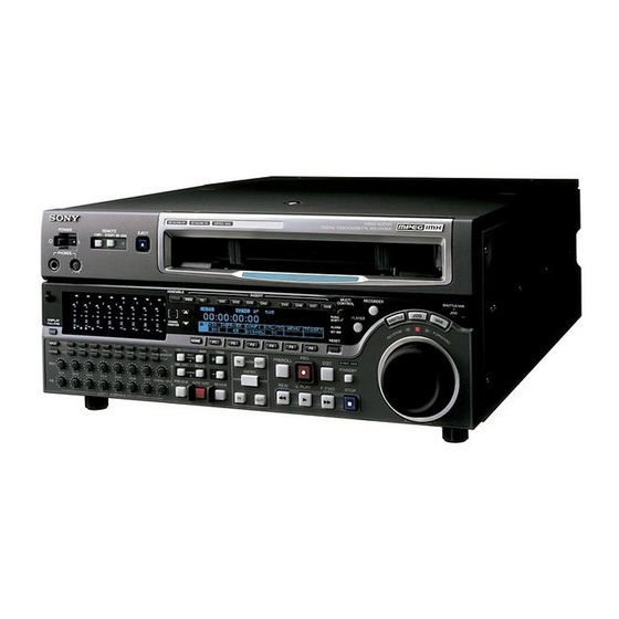
Digital videocassette recorder
Hide thumbs
Also See for MSW-A2000P:
- Operation manual (165 pages) ,
- Installation manual (48 pages) ,
- Operation manual (28 pages)

Related Manuals for Sony MSW-A2000P


Summary of Contents for Sony MSW-A2000P
- Page 1 DIGITAL VIDEOCASSETTE RECORDER MSW-A2000 MSW-A2000P MSW-M2000 MSW-M2000P MSW-2000 OPERATION MANUAL [English] 1st Edition (Revised 8)
- Page 2 WARNING For the customers in the USA This equipment has been tested and found to comply with the limits for a Class A digital device, pursuant to Part 15 of To prevent fire or shock hazard, do not the FCC Rules. These limits are designed to provide expose the unit to rain or moisture.
- Page 3 For the customers in Europe This product with the CE marking complies with both the EMC Directive (89/336/EEC) and the Low Voltage Directive (73/23/EEC) issued by the Commission of the European Community. Compliance with these directives implies conformity to the following European standards: •...
-
Page 5: Table Of Contents
Table of Contents 1-1 Features ................... 1-1 Chapter 1 1-2 Example System Configuration ............ 1-4 Overview 2-1 Control Panels ................2-1 Chapter 2 2-1-1 Upper Control Panel ............... 2-2 Location and Function 2-1-2 Lower Control Panel ............... 2-3 of Parts 2-1-3 Switch Panel ................. - Page 6 Table of Contents 5-3 Special Automatic Editing Methods ........... 5-13 Chapter 5 5-3-1 Quick Editing ............... 5-13 Editing (Continued) 5-3-2 Continuous Editing .............. 5-13 5-3-3 Standalone Editing ............... 5-14 5-3-4 Manual Editing ..............5-14 5-3-5 Preread Editing ..............5-14 6-1 Overview ..................6-1 Chapter 6 6-2 Shot Mark Operation Menu ............
-
Page 7: Features
1-1 Features The MSW-A2000/A2000P/M2000/M2000P/2000 is a High-performance heads and compatibility digital videocassette recorder based on the MPEG playback function IMX format. This unit uses large scale integrated circuits for signal The newly developed high-performance heads and processing, and has a simple internal construction, dynamic tracking (DT) technology provide high- allowing it to provide functionality at least equivalent density recording and playback in narrow tracks with... - Page 8 1-1 Features High image quality MPEG-2 intraframe Basic operation buttons and jog/shuttle encoding at 50 Mbps. dial The video signal compression uses MPEG-2 The basic buttons and jog/shuttle dial for VTR and intraframe encoding conforming to 4:2:2 Profile @ editing operations are provided in the conventional Main Level, with a 1:3.3 compression ratio;...
- Page 9 High quality variable speed playback and Tele-File functions digital jog sound function Tele-File enables data writing/reading between cassettes with memory labels and VTRs. It increases In digital BETACAM or MPEG IMX format playback, the efficiency of operations such as recording, the dedicated playback DT heads allow smooth, playback and editing, and source data management.
-
Page 10: Example System Configuration
1-2 Example System Configuration 1-1 Features The following conceptual diagram shows an example of use. Microphone BVE-series editor Tape control Digital/analog cassette SDTI-CP Audio/video server system MSW-A2000/A2000P/M2000/M2000P/2000 Video monitor Analog composite Analog composite/component Analog audio Audio monitor VTR with SDI connectors or analog VTR Chapter 1 Overview... -
Page 11: Location And Function Of Parts
2-1 Control Panels There are three control panels, as follows: • Upper control panel • Lower control panel • Switch panel Upper control panel (see page 2-2) VID. IN PB/EE CONFI CTL/TC MENU TCGSET Y-R,B Lower control panel (see page 2-3) Switch panel (access by opening the lower control panel) (see page 2-15) CONTROL PANEL KEY INHI... -
Page 12: Upper Control Panel
2-1 Control Panels 2-1-1 Upper Control Panel 1 POWER switch 2 REMOTE buttons and RS-232C indicator 3 EJECT button Cassette compartment 4 Format indicators BETACAM/SP BETACAM SX MPEG IMX Digital BETACAM REMOTE POWER EJECT 1(9P) 2(50P) RS-232C PHONES 5 PHONES jack and control 1 POWER switch 4 Format indicators Pressing the ‘... -
Page 13: Lower Control Panel
2-1-2 Lower Control Panel 4 Time data/menu display section (see page 2-7) 2 CHANNEL CONDITION 5 MULTI CONTROL knob and SHIFT indicator (see page 2-6) indicator (see page 2-8) 1 Audio control section 6 RESET button (see page 2-9) 3 Menu control buttons (see page 2-4) (see page 2-7) VID. - Page 14 2-1 Control Panels 1 Audio selection function selector buttons 1 Audio control section INPUT (input signal selection mode) button: Pressing this button puts the unit into input signal 1 Audio selection function selector buttons selection mode. In the audio setting display section, indicators flash to indicate the currently 2 DISPLAY FULL/FINE button selected signal for each channel (SDI, AES/EBU,...
- Page 15 Input channel indicator: Indicates the input channel 3 Audio setting display section from which audio signals are recorded on the Input signal indicator audio track. Two numbers light to indicate that SDI SDTI signals from the corresponding input channels are DATA indicator AES/EBU/ANA DATA 5 6 7 8...
- Page 16 2-1 Control Panels About the CH8/ALL CH (channels) control in the Note REC control row Before selecting signals from two input channels You can choose to use the rightmost CH8/ALL CH for recording in one recorder channel, check to be control in the REC control row to adjust the recording sure that the emphasis settings (ON or OFF) of the level of all channels.
- Page 17 1 Time data display 3 Menu control buttons This displays indicators relating to time data and other indicators. These buttons are used for function menu (see the following section “Overview of the function menu”) Time data display area 1 and setup menu (see Chapter 9) operations. The page Time data type indicator buttons (V, v, and HOME) select menu pages, and the DF indicator...
- Page 18 2-1 Control Panels VITC indicator CONFI (ON)/PREREAD indicators Regardless of the display in time data display These indicate the state of the VTR CONFI playback area 1, this indicator lights when VITC values are function. When the CONFI playback function is being read or recorded.
- Page 19 Speed indication area 1 SHUTTLE button This indicates the speed of a DMC playback. To use the search dial for playback in shuttle mode, During a DMC playback, “DMC SPD” is displayed in press this button, turning it on. time data display area 2. For details of playback in shuttle mode, see the description of the search dial 5.
- Page 20 2-1 Control Panels Playback modes using the search dial 8 REC INHI (recording inhibit) indicator Playback mode Operations and functions Shuttle Press the SHUTTLE button or the This indicator is on or off according to the search dial so that the SHUTTLE combination of the F5 (RECINH) setting on function button lights, then turn the search dial.
- Page 21 2 REC (record) button 5 STOP button To start recording, press this button together with the To stop recording or playback, press this button, PLAY button, turning it on. turning it on. When you stop playback, the unit switches either to Monitoring in E-E mode still playback or to E-E mode according to the setting When the unit is in stop mode, pressing the REC...
- Page 22 2-1 Control Panels To switch between the 16-bit/8-channel mode and 24-bit/4- q; Editing mode setting section channel modes for audio recording, refer to the Maintenance Manual, Volume 1. 1 ASSEMBLE button qa ALARM indicator and KEY INHI ASSEMBLE INSERT indicator VIDEO ALARM indicator This lights when a hardware error is detected on the...
- Page 23 4 TRIM buttons qd Editing control section Use these buttons to trim an edit point to single-frame precision. Hold down the IN, OUT, AUDIO IN, or AUDIO OUT 1 DMC/FEED button button, and press one of these buttons. The ‘+’ button 2 MEMORY indicator advances the corresponding edit point by one frame, 3 DELETE button...
- Page 24 2-1 Control Panels 7 AUTO (automatic) EDIT button After edit point setting, to carry out automatic editing (recording), press this button, turning it on. If the IN point is not set, the automatic editing is carried out with the point where you pressed this button as the IN point.
-
Page 25: Switch Panel
2-1-3 Switch Panel To access the switch panel, open the lower control On how to open the lower control panel, see the figure on page 2-1. panel. 1 Memory card slot (MSW-A2000/A2000P/M2000/M2000P only) 2 Memory card ejection button 3 CONTROL PANEL connector CONTROL PANEL KEY INHI PANEL SEL... -
Page 26: Connector Panel
2-2 Connector Panel Cooling fan 2 Analog video input/output section (see page 2-17) 1 Analog audio input/output 3 Digital audio input/output section (see page 2-17) section 4 Digital signal input/ output section (see page 2-18) Cooling fan 5 Power supply section (see page 2-18) 7 Time code input/output section (see page 2-19) - Page 27 5 COMPOSITE VIDEO OUTPUT connectors 2 Analog video input/output section (BNC type) These connectors output analog composite video 1 REF.VIDEO INPUT connectors and 75 Ω termination switch signals. When the setting of F4 (CHARA) in function menu 2 COMPOSITE VIDEO INPUT connectors page 4 is ON, connector 3 (SUPER) outputs a signal and 75 Ω...
- Page 28 2-2 Connector Panel 4 Digital signal input/output section 5 Power supply section INPUT 1 AC IN connector 1 SDI INPUT connectors 2 Ground terminal SDTI-CP OUTPUT INPUT 1 AC IN connector 2 SDTI-CP INPUT connector Use the optional power cord to connect this to an AC OUTPUT outlet.
- Page 29 2 CONTROL PANEL connector (round type, 10- 7 Time code input/output section pin) In addition to the lower control panel, a similar control panel can be connected to this unit. To connect such a 1 TIME CODE IN connector second control panel, use this connector. When two control panels are connected, use the PANEL SELECT TIME CODE switch on the switch panel (see page 2-15) to specify...
- Page 30 2-2 Connector Panel 2 MONITOR OUTPUT L connector (XLR 3-pin, male) This outputs the audio signals whose output destination was set to ‘L’ with the audio signal selection buttons in the audio control section. If multiple tracks have been set to ‘L’, the signals of those tracks are mixed for output.
-
Page 31: Connections To External Devices
3-1 Connections to External Devices 3-1-1 Connections to Digital Devices This unit can input serial digital signals (video and A500/A500P/500/500P. The following example shows audio) from another digital VTR such as the DNW-75/ the connections with a DNW-A75/A75P unit as a 75P/65/65P, DNW-A75/A75P/A65/A65P and DVW- player, with this unit used as recorder. -
Page 32: Connections To Analog Devices
3-1 Connections to External Devices 3-1-2 Connections to Analog Devices The following example shows the connections with an analog VTR (a Betacam SP VTR, D2 VTR, 1-inch VTR, etc.) for recording analog audio and video signals. Video monitor 75 Ω termination switch: Set to OFF when using an analog composite video signal bridge connection, and otherwise to ON. -
Page 33: Connections Using The Sdti-Cp Interface
3-1-3 Connections Using the SDTI-CP Interface The following examples show the connections with dubbing video and audio signals. devices that support the SDTI-CP interface for • When this unit is used as player Reference signal 75Ω termination switch: ON VIdeo monitor REF. -
Page 34: Reference Signals For Video Output And Servo System
3-2 Reference Signals for Video Output and Servo System This section describes how reference signals for the The output from the internal reference video signal video output signals and servo system are selected. generator is supplied to the output video signal and servo circuits as a reference signal. -
Page 35: Reference Signal For The Servo System
3-2-2 Reference Signal for the Servo System The VTR automatically selects either the input video system. Which of the two signals is selected depends signal or the output from the internal reference video on the operational status of the VTR, as shown in the signal generator as the reference signal for the servo following flowchart. -
Page 36: Connecting Reference Signals
3-2 Reference Signals for Video Output and Servo System 3-2-3 Connecting Reference Signals Connect reference signals as shown below, according to the way in which the unit is to be used. • Connections for recording from a switcher or signal generator Reference signal Switcher or signal generator 75 Ω... - Page 37 • Connections for playback Reference signal Video monitor 75 Ω termination switch: ON • SDI OUTPUT • COMPOSITE REF. VIDEO • COMPONENT INPUT MSW-A2000/A2000P/M2000/M2000P/2000 Chapter 3 Preparations...
-
Page 38: Setup
3-3 Setup The principal setup operations before operating this unit can be carried out using setup menus. The setup menus of this unit comprise a basic setup menu and an extended setup menu. The contents of these menus are as follows. Basic setup menu: •... -
Page 39: Superimposed Character Information
3-4 Superimposed Character Information When the function menu item CHARA is set to ON, Adjusting the character display the video signal output from the COMPOSITE VIDEO OUTPUT 3 (SUPER) connector or the SDI OUTPUT You can adjust the position, size and type of the 3 (SUPER) connector contains superimposed character superimposed characters using setup menu items 002, information, including time code, menu settings, and... - Page 40 3-4 Superimposed Character Information 2 Time code reader drop frame mark (for 525-line Display Operation mode mode only) Block A Block B “.”: Indicates drop frame mode (speed) Feed playback speed setting “:”: Indicates non-drop-frame mode (+1.00 or +2.00 (BKMW-105 installed)) 3 Time code generator drop frame mark (for 525- FEED...
-
Page 41: Cassettes
3-5 Cassettes 3-5-1 Cassette Types 3-5-2 Inserting and Ejecting Cassettes This unit uses the following MPEG IMX cassettes for both recording and playback. It is not possible to insert or eject a cassette unless the unit is powered on. MPEG IMX cassettes Small cassettes BCT-6MX/12MX/22MX/32MX/60MX Inserting a cassette Large cassettes BCT-64MXL/94MXL/124MXL/184MXL... -
Page 42: Preventing Accidental Erasure Of Recordings
3-5 Cassettes Removing slack from the tape Press in one of the reels with a finger, and turn gently in the direction shown by the arrows until there is no slack in the tape. Ejecting a cassette Press the EJECT button. Note Ejecting is a local operation. -
Page 43: Using A Memory Stick
3-6 Using a Memory Stick When a Memory Stick is inserted in the VTR, the file Types of Memory Stick data can be stored on the Memory Stick, which enables you to share data among VTRs. There are two types of Memory Stick: MagicGate Memory Stick that are equipped with the MagicGate copyright protection technology and general Memory Inserting a Memory Stick... - Page 44 Do not turn off the power of the unit or remove the Memory Stick. This may damage the data. For details, refer to the Maintenance Manual. Memory Stick and are the trademarks of Sony Corporation. MagicGate Memory Stick and are the trademarks of Sony Corporation. 3-14 Chapter 3 Preparations...
-
Page 45: Recording And Playback
4-1 Recording This section describes video and audio recording on the unit. 4-1-1 Preparations for Recording For details on each setting, see the pages indicated in Switch and menu settings parenthesis. Before beginning recording, make necessary switch and menu settings. POWER switch: ‘... -
Page 46: Recording Time Code And User Bit Values
4-1 Recording Adjusting the audio recording levels To use the emphasis function When carrying out audio recording at a To add emphasis to the analog input audio signal or reference level analog playback audio signal, set the EMPHSS to ON Leave the REC controls pressed in. - Page 47 Setting an initial time code value Setting the time code value to the real time Use the following procedure. With the settings in function menu page 1 set as follows, carry out the procedure under the heading above, “Setting an initial time code value”. In steps 3 and 4, set the value slightly after the current time, then RESET button carry out step 6 at the instant the real time catches up...
- Page 48 4-1 Recording • When synchronizing to the time code (SMPTE To synchronize the internal time code RP188) in an SDI signal: generator to an external signal With the VID.IN in function menu HOME page, select SDI. Use this method to synchronize the time code •...
-
Page 49: Recording Procedure
To record an external time code without 4-1-3 Recording Procedure modification To record, use the following procedure. Using this method has no effect on the running of the internal time code generator. To record the playback time code from an external VTR, the method under the heading above, “To synchronize the internal time code generator to an external signal”, is recommended. -
Page 50: Playback
4-2 Playback This section describes playback of video and audio. 4-2-1 Preparations for Playback For details on each setting, see the pages indicated in Switch and menu settings parenthesis. Before beginning playback, make necessary switch and menu settings. POWER switch: ‘ & ’ side (ON) REMOTE buttons (see page 2-2) : off Audio signal selection buttons (see page 2-5) : Select the audio channel(s) to be monitored. -
Page 51: Playback Procedures
• Playback using the capstan override function Time data selection The playback speed is adjusted temporarily according to the angular position of the search dial, to align the Displayed time data playback phase with that of another VTR. Use the CTL/TC setting in function menu HOME page •... - Page 52 4-2 Playback Playback in jog mode Playback in shuttle mode In jog mode, you can control the speed of playback by In shuttle mode, you can control the speed of playback the speed of turning the search dial. The playback by the angular position of the search dial.
- Page 53 To alternate between normal-speed playback To alternate between normal-speed playback and shuttle mode playback and variable speed mode playback Set the search dial to the position corresponding to the Set the search dial to the position corresponding to the desired shuttle playback speed, then switch between desired variable playback speed, then switch between normal-speed playback and shuttle playback by normal-speed playback and variable speed playback by...
- Page 54 4-2 Playback Carrying out playback in feed mode When the adjustment is completed, release the Use the following procedure to carry out feed mode PLAY button. playback. The tape transport returns to normal speed, and the Speed display area SERVO indicator comes on again. To perform continuous capstan override playback Set setup menu item 111 (TSO PLAY) to FEED.
- Page 55 Auto feed playback Auto feed playback is a function for feed mode playback of the segment between a specified IN point and OUT point. By connecting this unit to a recorder VTR with a RECEIVE STANDBY function (MAV-555/2000 etc.) via the SDTI-CONTROL PANEL interface and executing auto feed playback on this unit, you can record the interval between the IN and OUT points on the recorder.
-
Page 56: Dynamic Motion Control (Dmc) Playback
4-2 Playback 4-2-3 Dynamic Motion Control (DMC) Playback Overview DMC playback allows you to vary the playback speed For example, during a live broadcast of a sporting for a certain section of a tape, in variable speed mode event you can set the start and end points of highlights (from –1 to +3 times normal speed for digital Betacam while recording, and then provide immediate DMC playback, from –1 to +3 times normal speed for MPEG... - Page 57 Holding down the DMC/FEED button, turn the Executing DMC Playback search dial, to set the initial speed at the playback start point. There are two methods of starting DMC playback. • Starting playback at the on-air cue from the on-air The speed you set appears in the speed indication start point area.
- Page 58 4-2 Playback To start playback immediately after preroll Press the PREVIEW button. The PREVIEW button lights, and after preroll, DMC playback is carried out for the section from the speed variation start point, then playback continues at normal speed from the speed variation end point. To stop the tape during DMC playback Press the STOP button.
-
Page 59: Automatic Editing
5-1 Automatic Editing This section describes how to carry out automatic Sequence of editing operations editing with this unit and another VTR connected to the REMOTE1-IN(9P) connector. The following flowchart outlines the sequence of operations in automatic editing with two VTRs. 5-1-1 Overview Selecting the editing mode (page 5-3) Editing mode... -
Page 60: Switch And Menu Settings
5-1 Automatic Editing 5-1-2 Switch and Menu Settings Before beginning editing, make necessary switch and menu settings. Recorder settings POWER switch: ‘ & ’ side (ON) REMOTE buttons (see page 2-2) : 1(9P) Editing mode setting section (see page 5-3) : Select assemble editing or insert editing. VID.IN setting (see page 8-3) : Select the input video signal. -
Page 61: Selecting The Editing Mode
Press the RECORDER button or PLAYER button 5-1-3 Selecting the Editing Mode to select the VTR on which you will set the edit point. To select the editing mode Select assemble editing or insert editing. The button which you have pressed lights. ASSEMBLE button Turn the search dial in jog or shuttle mode, and position the tape at the required edit point. - Page 62 5-1 Automatic Editing Note Setting split edit points During split editing, if you set six or more edit points for the recorder and player, the DELETE button starts In split editing, you can set the edit points for audio to flash, to indicate that such a setup is impossible. and video independently.
- Page 63 When the audio IN point is not set for insert To display the duration of an edit segment editing of audio only As long as the audio OUT point is set, the VTR is You can display the duration between two edit points ready for preview or editing.
-
Page 64: Modifying And Deleting Edit Points
5-1 Automatic Editing Deleting an edit point 5-1-5 Modifying and Deleting Edit Points To delete an edit point, use the following procedure. You can use the same procedure whether or not the If the edit points are not set correctly, for example if an DELETE button is flashing. -
Page 65: Cue-Up To Edit Points And Preroll
5-1-6 Cue-Up to Edit Points and 5-1-7 Preview Preroll When you have set the edit points, the PREVIEW button flashes, indicating that you can carry out a To preroll to a position before an edit IN point or cue preview. up to any edit point, use the following procedure. -
Page 66: Carrying Out Automatic Editing
5-1 Automatic Editing • From the OUT point to the postroll point, you can Monitor output monitor the playback from the recorder. During a preview, on a monitor connected to the The following figure illustrates this. recorder you can monitor the following video and audio. - Page 67 The following figure illustrates this. IN point OUT point Playback Playback E-E mode (recorder) (recorder) (player) Using a single monitor for video and audio OUT button on both player and recorder ENTRY button REVIEW button For efficient editing if only one monitor is available, use the following method.
- Page 68 5-1 Automatic Editing After automatic editing, to adjust the edit points and reexecute the edit Hold down the DELETE button and press the ENTRY button to recall the edit points. After adjusting the edit points, press the AUTO EDIT button to carry out the edit again.
-
Page 69: Dmc Editing
5-2 DMC Editing By controlling the player playback speed from the recorder you can achieve variable speed editing. 5-2-1 Overview of DMC Editing Conditions for DMC editing Tape movement during DMC editing DMC editing can be used for insert or assemble The following figure illustrates how the tapes move on editing, but not for audio split editing. -
Page 70: Carrying Out Dmc Editing
5-2 DMC Editing When the initial speed setting is complete, release 5-2-2 Carrying Out DMC Editing the DMC/FEED button. Press the PREVIEW button. Setting the edit points and player speed The tape is prerolled and then the recorder starts Use the following procedure. operating at normal speed and the player at the set initial speed. -
Page 71: Special Automatic Editing Methods
5-3 Special Automatic Editing Methods This section describes the following automatic editing 5-3-2 Continuous Editing methods: • Quick editing After an automatic editing operation, the recorder • Continuous editing automatically returns to the OUT point. For the • Standalone editing second and subsequent editing operations, you can •... -
Page 72: Standalone Editing
5-3 Special Automatic Editing Methods At the editing end point (the recorder OUT point), 5-3-3 Standalone Editing press the PLAY button. This refers to editing using as the player an external Editing ends, and the recorder continues with device which cannot be controlled remotely through playback. - Page 73 Notes • In preread editing, if an input video signal is used as the reference signal for the output video signal, this forms a feedback loop. To prevent the occurrence of feedback, set the OUTREF in function menu page 4 to REF, and set item 309 in the extended setup menu to AUTO 1 so as to use an external reference signal.
-
Page 75: Overview
6-1 Overview This unit can record shot marks or use shot marks Shot marks are indications at desired points on a tape recorded in MPEG IMX or Betacam SX format. which enable faster cueing. Types of shot mark This unit supports the following three types of shot post marks, treating them as varieties of shot marks. -
Page 76: Shot Mark Operation Menu
6-2 Shot Mark Operation Menu This section describes the settings in the shot mark Details of the shot mark operation menu operation menu. The shot mark operation menu comprises four items, G01 to G04. The detailed contents appear in the Displaying the shot mark operation menu following table. -
Page 77: Shot Mark Operations
6-3 Shot Mark Operations This section describes the operations concerning Reading shot marks from more than one reading and writing shot marks. Note that the cassette following operations cannot be carried out by remote control. After changing the cassettes, carry out the reading operation again. -
Page 78: Shot Mark List Operations
6-3 Shot Mark Operations To write in crash recording or assemble Erasing a shot mark editing Select the shot mark from the shot mark list, and then Hold the MARK button down for at least 2 carry out the deletion operation. seconds. - Page 79 A virtual shot mark appears on the monitor as “V- Example of list display MARK xxx” (xxx is the number). This is not written to the tape. The following figure shows how the list is organized. After entering a virtual shot mark, if you change the cassette or power the unit off, it appears in the list as the first shot mark of the next group read in.
-
Page 80: Cueing Up To Shot Marks
6-3 Shot Mark Operations To delete an individual shot mark With no shot mark list displayed, hold the MARK Use the following procedure. button down for at least 2 seconds. The REC/ERASE indicator lights, indicating that you can rewrite or erase shot marks. Display the shot mark list. -
Page 81: Reading In Shot Data
The tape is played back, and the shot data displayed. Cueing up to shot marks adjacent to the current tape position (index function) To delete the shot data Once again hold down the ENTRY button, and press In item G01 of the shot mark operation menu the PLAY button. -
Page 82: Sorting Shot Marks
6-3 Shot Mark Operations 6-3-6 Sorting Shot Marks Based on shot data recorded on the tape, you can With the shot mark list displayed, press the F5 separate the shot marks by cassette, and sort them in (SETING) button. time code sequence. Press the F2 (NEXT) button, and select SORTING To sort the shot marks LIST. -
Page 83: Overview Of Tele-File Functions
7-1 Overview of Tele-File Functions Tele-File is a non-contact data carrier system. Data management in clip units Tele-File increases the efficiency of data management and operations such as recording, playback, and In Tele-File, data is managed in units called “clips.” A editing by enabling information to be exchanged clip consists of the following data items, whose between VTRs with data reading and writing functions... -
Page 84: Opening The Tele-File Menu
7-2 Opening the Tele-File Menu Opening from the function menu Configuration of the Tele-File menu Display page 5 of the function menu in the menu The Tele-File menu has a tree structure, as illustrated display section, and then press the F1 (TELE-F) below. -
Page 85: Tele-File Menu
7-3 Tele-File Menu 7-3-1 Clip Data Display For more information about how to display menus on the How to read the display monitor, see the section “To display menus on the monitor” (page 9-2). Shown below are examples of the default menu displays in the menu display section and the monitor display. - Page 86 7-3 Tele-File Menu Setting display area Menu items (functions) Displays the setting of the currently selected data type, Display menu items (functions). and a cursor (“*” or “>”). These are common for all of the data items in clip data The meaning of the cursor symbols is as follows: display mode.
- Page 87 Title To select clips The title (maximum 14 characters) set in attribute data display/modify mode. Rotate the MULTI CONTROL knob in clip data display mode. Selected clip number The data for the selected clip appears in the menu A 4-digit number representing the number of the display section, where it is selected.
- Page 88 7-3 Tele-File Menu Moving the cursor directly To cue up the cue point, IN point, or OUT point Regardless of the cursor’s current position, pressing one of the following buttons moves the cursor directly Select a clip. to the specified position in the same clip and displays the data.
-
Page 89: Modifying Clip Data
7-3-3 Modifying Clip Data To modify clip data, put the unit into clip data display The function assignments for menu items in clip data mode and then press the F2 (SELECT) button to put it modification mode are as follows. into clip data modification mode (the cursor changes to “>”). - Page 90 7-3 Tele-File Menu To add and delete clips To set time code data To add clips Proceed as follows to make or change settings for cue point, IN point, and OUT point data. Rotate the MULTI CONTROL knob to move the “*”...
- Page 91 To set the set or modified data as other time To make take number, cut number, and data scene number settings Press the F6 (SET TO) button and select the time data (cue point, IN point, or OUT point), and then Proceed as follows to make take number, cut number, press the F5 (SET) or F6 (SET NL) button.
-
Page 92: Undo/Resume Functions
7-3 Tele-File Menu To make comment settings 7-3-4 Undo/Resume Functions Proceed as follows to make comment settings. Undo function The undo function cancels all modifications and Select a clip. returns the data to the state it was in when first read. Press the F5 (UNDO) button in clip data display mode. -
Page 93: Displaying And Modifying Attribute Data
7-3-5 Displaying and Modifying Attribute Data You can display and modify attribute data. The example below shows attribute data displayed on the monitor. TELE-FILE INFORMATION Video final recording date *REC DATE 2001/07/21 TITLE TEST 01 Administrator data ADMIN MODEL SERIAL 00000 WRITE INHIBIT OFF THREAD COUNT 00012... - Page 94 7-3 Tele-File Menu Press the F2 (OK) button. To modify attribute data All modifiable data is erased. You can modify the title, ID, administrator data, and write inhibit setting attributes. Note However, the attributes cannot be modified when the In the following cases, the FORMAT item does not write inhibit setting is ON.
-
Page 95: Overview
8-1 Overview The function menu allows you to make frequently HOME2 page (user-defined function keys) made settings, such as selection of input video signals and time code settings. Up to six function keys can be defined (i.e. six functions can be assigned to the F1 to F6 buttons in the HOME2 page). -
Page 96: Using The Function Menu
8-1 Overview 8-1-2 Using the Function Menu To change a menu item setting To change a menu item setting, press the corresponding function button (F1 to F6) to display the desired setting in the lower part of the menu display. Each press of the button displays the next setting. -
Page 97: Function Menu Item List
8-2 Function Menu Item List The function menu has the following items. HOME page Item Setting F1 (VID.IN) Selects the input video signal. COMPST: Analog composite signal Y-R,B: Analog component signal SDI: SDI signal SDTI: SDTI-CP signal SG (normally not displayed): Test signal from the internal test signal generator (For details, see setup menu item 710 on page 8-19.) F2 (PB/EE) Selects the video and audio signals output during fast forward, rewind, stop, and standby. - Page 98 8-2 Function Menu Item List Page 1 Item Setting F1 (TCG) Selects the time code to use. INT: Time code generated by the internal time code generator EXT: One of the following time codes • When F6 (TCR) is set to LTC or AUTO, the external time code input from the TIME CODE IN connector •...
- Page 99 Page 2 Item Setting F1 (V.PROC) Selects the control method for the internal digital video processor. LOCAL: Change the settings of the internal digital video processor by using this function menu. REMOTE: Use the optional BVR-50/50P Remote Control Unit to control the internal digital video processor.
- Page 100 8-2 Function Menu Item List Page 3 Setting Item F1 (SYNC) Sets the output signal sync phase. Setting method With the displayed setting flashing, you can rotate the MULTI CONTROL knob to adjust the output signal sync phase across the range ±15 µs relative to this unit’s input reference signal. Adjust this item when you want to adjust the output signal sync phase precisely to match a reference signal, or when connecting this unit and other VTRs to a device such as a switcher to perform operations such as special effects editing.
- Page 101 Page 4 Item Setting F1 (CAPSTN) Selects the number of fields for capstan lock in playback and editing. In 525/60 mode 2F: The capstan servo locks in units of 2 fields. • For tape output, color framing may not match the reference signal selected with the F2 (OUTREF). •...
- Page 102 8-2 Function Menu Item List Item Setting F5 (RECINH) Specifies whether or not to inhibit recording to tape. ON: Inhibit recording to tape depending on the setting of setup menu item 310. OFF: Do not inhibit recording to tape. F6 (PREREAD) Specifies whether or not to preread (read before write) in insert editing.
-
Page 103: Setup Menu Configuration
9-1 Setup Menu Configuration Configuration of the extended setup menu This unit has the following setup menus. The extended setup menu comprises the following • Basic setup menu groups of items. • Extended setup menu To access the extended setup menu, a setting on the Refer to Item group Function... -
Page 104: Setup Menu Operations
9-2 Setup Menu Operations To display menus on the monitor To display setup menus Setting CHARA to ON in function menu page 4 allows you to display setup menus on the monitor connected to the COMPOSITE VIDEO OUTPUT 3 (SUPER) ASSEMBLE MULTI connector or SDI OUTPUT 3 (SUPER) connector of... - Page 105 To display a desired sub-item To change the settings of menu items with sub-items For a menu item having sub-items, you can select a desired sub-item as follows. When a selected menu item has sub-items, select a desired sub-item using the procedure described in the section “To display a desired sub-item”...
- Page 106 • When the MSW-A2000 is used in the 625-line mode or when the MSW-A2000P is used in 525-line mode, Recall (B02) analog tape can only be played back in the simple Menu bank 2 Save (B12) playback mode.
-
Page 107: Items In The Basic Setup Menu
9-3 Items in the Basic Setup Menu The basic setup menu contains the following items. In the “Settings” column of the table, the factory default settings are indicated by an enclosing box. Item number Item name Settings PREROLL TIME 0S ... 5S ... 30S: Set the preroll time to between 0 and 30 seconds. A preroll time of at least 5 seconds is recommended when using this unit for editing. - Page 108 (These are different from the settings for the mode before switching.) • When the MSW-A2000 is used in 625-line mode or when the MSW-A2000P is used in 525-line mode, analog tape can only be played back in the simple playback mode.
- Page 109 Item number Item name Settings When MAP is selected in menu item 006, the buttons that can be operated on the LOCAL KEY MAP control panel of this unit when it is being controlled by remote control from another device can be selected from the following sub-items. The settings of each sub-item are as follows.
-
Page 110: Items In The Extended Setup Menu
9-4 Items in the Extended Setup Menu 9-4 Items in the Extended Setup Menu In the “Settings” column of the table, the factory The extended setup menu contains the following items. default settings are indicated by an enclosing box. Menu items in the range 100 to 199, relating to the control panels Item number Item name Settings SELECTION FOR... - Page 111 Menu items in the range 100 to 199, relating to the control panels (Continued) Item number Item name Settings REC INHIBIT LAMP Select whether or not to flash the REC INHI indicator when the function menu FLASHING item RECINH is set to OFF and the record inhibit plug on the cassette is pressed OFF : Do not flash the REC INHI indicator.
- Page 112 9-4 Items in the Extended Setup Menu Menu items in the range 100 to 199, relating to the control panels (Continued) Item number Item name Settings KEY INHIBIT SWITCH Select which switches and buttons can be operated when the KEY INHIBIT switch on the switch panel is set to ON.
- Page 113 Menu items in the range 100 to 199, relating to the control panels (Continued) Item number Item name Settings AUDIO PB VOLUME Select whether each of the audio PB controls on the lower control panel is effective to control the audio playback level on each channel or the CH8/ALL CH control alone functions as a master control to control the audio playback level on all channels together.
- Page 114 9-4 Items in the Extended Setup Menu Menu items in the range 300 to 399, relating to editing operations Item number Item name Settings VAR SPEED RANGE FOR Select the playback speed range when carrying out playback in variable speed SYNCHRONIZATION mode from a remote control unit connected to the REMOTE-1 IN(9P) connector or REMOTE-1 OUT (9P) connector.
- Page 115 Menu items in the range 300 to 399, relating to editing operations (Continued) Item number Item name Settings Select the STD or NON-STD mode in accordance with a composite video input. SELECTION OF STD/ NON-STD FOR AUTO : Detect automatically whether the input video luminance and chrominance COMPOSITE VIDEO IN signals are interleaved or not.
- Page 116 9-4 Items in the Extended Setup Menu Menu items in the range 300 to 399, relating to editing operations (Continued) Item number Item name Settings AUDIO EDIT MODE Select the type of audio transition used for digital audio editing. CUT: Cut editing (audio discontinuity at transition point, and possible noise during playback).
- Page 117 Menu items in the range 300 to 399, relating to editing operations (Continued) Settings Item number Item name DIGITAL AUDIO EDIT Select how to apply digital audio edit preset from an external controller. PRESET REPLACE NODEF : Apply edit preset for channels 1 to 8 from external controller to tracks 1 to 8, correspondingly.
- Page 118 9-4 Items in the Extended Setup Menu Menu items in the range 500 to 599, relating to tape protection Item number Item name Settings Select the time delay from the tape transport stopping (either the “stop mode” or STILL TIMER the still playback mode in search mode) until the unit automatically switches to the tape protection mode, in order to protect the video heads and the tape.
- Page 119 Menu items in the range 600 to 699, relating to the time code generator (Continued) Item number Item name Settings VITC POSITION SEL-2 In 525-line mode Select a line to insert the VITC in. 12H ... 18H ... 20H: Select any line from 12 to 20. Note You can insert the VITC signal in two places.
- Page 120 9-4 Items in the Extended Setup Menu Menu items in the range 600 to 699, relating to the time code generator (Continued) Item number Item name Settings U-BIT BINARY GROUP Select the user bits to be used in the time code generated by the time code FLAG generator.
- Page 121 Menu items in the range 700 to 799, relating to video control Item number Item name Settings SELECTION OF VIDEO/ In E-E mode the video signal is output delayed with respect to the video input SYNC DELAY signal by the time for video circuit processing. With this item, select whether or not to delay the sync signal attached to the output video signal by an amount corresponding to the delay.
- Page 122 9-4 Items in the Extended Setup Menu Menu items in the range 700 to 799, relating to video control (Continued) Item number Item name Settings FORCED VERTICAL The “Y-add” function is normally switched on automatically during jog or variable INTERPOLATION OFF speed playback.
- Page 123 Menu items in the range 700 to 799, relating to video control (Continued) Item number Item name Settings VIDEO PROCESS ON When the function menu item CAPSTN or setup menu item 106 is set to 2F for 2- CAP LOCK 2FIELD field playback, select whether or not to carry out a “picture shift”.
- Page 124 9-4 Items in the Extended Setup Menu Menu items in the range 700 to 799, relating to video control (Continued) (Items 715 to 721: Settings for controlling the video processing system according to the menu settings.) Item number Item name Settings VIDEO GAIN CONTROL Adjust the video output level.
- Page 125 Menu items in the range 700 to 799, relating to video control (Continued) Item number Item name Settings H BLANKING WIDTH Select the horizontal blanking width of the video output signal. NAROW : Digital blanking (narrow) WIDE: Analog blanking (wide) When WIDE is selected, the horizontal blanking width complies with RS170A, and normally the blanking is widened and the image becomes narrower.
- Page 126 9-4 Items in the Extended Setup Menu Menu items in the range 800 to 899, relating to audio control Item number Item name Settings DIGITAL JOG SOUND Turns the digital jog sound on and off OFF: Digital jog sound is turned off. Audio of digital channels not subjected to speed correction is output.
- Page 127 Menu items in the range 800 to 899, relating to audio control (Continued) Settings Item number Item name AUDIO OUTPUT PHASE Select the output timing of digital audio playback signals: (SDI and AES/EBU only). The reference position corresponds to a setting of 80H; when the setting is less than 80H, the output timing is advanced, and when it is higher than 80H, the output timing is delayed.
- Page 128 9-4 Items in the Extended Setup Menu Menu items in the range 800 to 899, relating to audio control (Continued) Settings Item number Item name NAU FLG PB Controls the non-audio flag when the playback format is Digital Betacam or Betacam SX.
- Page 129 Menu items in the range 800 to 899, relating to audio control (Continued) Settings Item number Item name AES OUT SEL Select the audio signals to assign to AES/EBU audio output channels. Sub-item Note Check to be sure that the selected tracks are being output from the AES/EBU OUTPUT connectors.
- Page 130 9-4 Items in the Extended Setup Menu Menu items in the range 900 to 999, relating to digital processing Item number Item name Settings FREEZE MODE Select the freeze mode and freeze timing. FIELD: Freeze a video field. Field may be odd or even, according to the timing. FLD1: Freeze an odd field.
-
Page 131: Removing A Cassette When Tape Slack Occurs
10-2 Head Cleaning To clean the video heads and audio heads, always use Notes the special-purpose Sony BCT-HD12CL cleaning • When carrying out head cleaning without using the cassette. automatic cleaning function, be sure to eject the... -
Page 132: Error Messages
• To display error messages and codes superimposed If an error message appears, contact your Sony service on the monitor, set the CHARA in function menu representative. - Page 133 Error Message List Code Message Description – NO COMMUNICATION Abnormality in the interface between the lower control panel (KY-464/465 board) and SYS CPU (SS-89 board) has been detected in the lower control panel side. REEL TROUBLE Tape slacking has been detected in the threading or unthreading operation. REEL TROUBLE Tape slacking or tape breaking has been detected in the SEARCH, FF,or REW mode.
-
Page 134: Moisture Condensation
10-4 Moisture Condensation When the unit is suddenly moved from a cold to a If this happens, the drum and capstan motors stop and warm location, or used in a very humid place, moisture the cassette is automatically ejected. Then, the durm from the air can condense on the head-drum. -
Page 135: Regular Checks
10-5 Regular Checks 10-5-1 Digital Hours Meter Displaying the hours meter The hours meter can display seven items of information, in corresponding display modes, about the MULTI CONTROL knob operational history of the unit. Use it as a guide in scheduling periodic maintenance. -
Page 136: Maintenance Timings
10-5 Regular Checks 10-5-2 Maintenance Timings Use the following table as a timing guide for checking Note that an arrow in the table means that the and replacing components of the unit. component to be replaced is part of the assembly the These intervals are not guaranteed lifetimes;... -
Page 137: Specifications
Specifications MPEG IMX record/playback time General 184 minutes with BCT-184MXL (525/60) Recording format MPEG IMX 220 minutes with BCT-184MXL Power requirements (625/50) 100 to 240 VAC, 50/60 Hz Betacam SX playback time Power consumption 194 minutes with BCT-194SXLA 2 A (200 W) (MSW-A2000/ Analog Betacam playback time (MSW-M2000/ A2000P) M2000P/A2000/A2000P) - Page 138 Specifications Analog composite input to analog composite Recommended tapes output MPEG IMX cassettes (S, L): BCT-6MX/12MX/22MX/32MX/ Bandwidth (Y) 0 to 5.75 MHz 60MX +0.5 dB/ –2.0 dB BCT-64MXL/94MXL/124MXL/ S/N ratio 53 dB or more 184MXL Differential gain 2% or less Digital Betacam cassettes (S, L) Differential phase 2°...
- Page 139 Digital Betacam playback (MSW-M2000/M2000P) Video MSW-M2000: 0 to 5.75 MHz +0.5 dB/–0.5 dB Bandwidth MSW-M2000P: 0 to 2.75 MHz +0.5 dB/–0.5 dB 0 to 2.75 MHz +0.5 dB/–0.5dB R–Y/B–Y S/N ratio 62 dB or more K factor 1 % or less Digital Audio (CH1 to CH4) 20 Hz to 20 kHz +0.5 dB/–1.0 dB Frequency response (0 dB at 1 kHz)
- Page 140 S/N ratio (at 3% distortion level) 85 dB or more Distortion (THD at 1 kHz reference 0.5% or less level a) Reference level: +4 dBm Analog Betacam playback (MSW-A2000P/M2000P) Video Metal tape Oxide tape Bandwidth 25 Hz to 5.5 MHz +0.5 dB/–4.0 dB 25 Hz to 4.0 MHz +0.5 dB/–6.0 dB...
- Page 141 TIME CODE IN XLR 3-pin, female (1) Chroma level ±3 dB/ –∞ to +3 dB selectable 0.5 to 18 Vp-p, 10 kΩ, balanced Setup level (MSW-A2000/2000) ±30 IRE Black level (MSW-A2000P/M2000P) Output connectors ±210 mV Y/C delay ±100 ns (in analog Betacam SDI OUTPUT...
- Page 142 Specifications Design and specifications are subject to change Remote connectors without notice. CONTROL PANEL 10-pin (2), female To prevent electromagnetic interference Front/rear selectable from portable communications devices REMOTE 1-IN(9P) The use of portable telephones and other D-sub 9-pin, female communications devices near this unit can result in REMOTE 1-OUT(9P) misoperations and interference with audio and video D-sub 9-pin, female...
-
Page 143: Index
Index Continuous editing 5-13 CONTROL PANEL connector 2-19 AC IN connector 2-18 F FWD button 2-11 Control panels 2-1 ALARM indicator 2-12 Features 1-1 CTL/TC (function menu) 8-3 ALL CH indicators 2-6 525/625 CUE OUT connector 2-16, A-5 Analog indicator 2-8 audio input/output section 2-16 switching 9-4 device connection 3-2... - Page 144 Index Menu Recording display 2-8 preparations 4-1 T INFO (function menu) 8-6 operation 2-7, 6-2, 8-1, 9-2 procedure 4-5 Tape transport control section 2-10 MIXING button 2-4 time code 4-2 TC button 2-12 Moisture condensation 10-4 REF. VIDEO INPUT connectors 2-17 TCG (function menu) 8-4 MONITOR OUTPUT connectors 2-19 Reference signals...
- Page 145 The material contained in this manual consists of information that is the property of Sony Corporation and is intended solely for use by the purchasers of the equipment described in this manual. Sony Corporation expressly prohibits the duplication of any...
- Page 146 MSW-A2000/A2000P Sony Corporation MSW-M2000/M2000P B & P Company MSW-2000 (SY, 2000 3-203-783-13(1)