Table of Contents
Advertisement
Quick Links
OWNER'S MANUAL
1500W Monoblock Subwoofer Amplifier
Thank you for purchasing a JL Audio amplifier for
your automotive sound system.
Your amplifier has been designed and manufactured to exacting
standards in order to ensure years of musical enjoyment in your vehicle.
For maximum performance, we highly recommend that you have
your new amplifier installed by an authorized JL Audio dealer. Your
authorized dealer has the training, expertise and installation equipment
to ensure optimum performance from this product. Should you
decide to install the amplifier yourself, please take the time
to read this manual thoroughly to familiarize yourself
with its installation requirements and setup procedures.
If you have any questions regarding the instructions in this
manual or any aspect of your amplifier's operation, please contact your
authorized JL Audio dealer for assistance. For additional information,
visit www.jlaudio.com/support.
Advertisement
Table of Contents

Related Manuals for JL Audio NexD RD1500/1


Summary of Contents for JL Audio NexD RD1500/1
- Page 1 For maximum performance, we highly recommend that you have your new amplifier installed by an authorized JL Audio dealer. Your authorized dealer has the training, expertise and installation equipment to ensure optimum performance from this product.
-
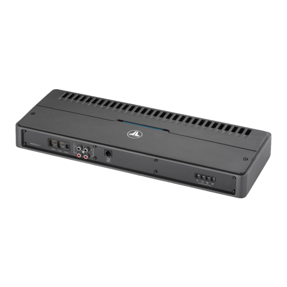
Page 2: Installation Applications
(pg. 6) Remote Turn-On Left & Right +12 V Power Connector Output Jacks Connector (pg. 6) (pg. 9) (pg. 5) Chassis Ground Left & Right Connector Input Jacks (pg. 5) (pg. 7) 2 | JL Audio - RD1500/1 Owner’s Manual... - Page 3 Cooling Efficiency Considerations: Safety Considerations: The outer shell of your JL Audio amplifier Your amplifier needs to be installed in a dry, is designed to remove heat from the amplifier well-ventilated environment and in a manner circuitry. For optimum cooling performance, which does not interfere with your vehicle’s safety...
-
Page 4: Product Description
(use of the JL Audio ECS master The RD1500/1 can be operated with a wide ground lug, XB-MGLU is recommended). Use variety of source units and system configurations. -
Page 5: Power Connections
For optimal grounding, we recommend the use of a JL Audio ECS master ground lug (XB-MGLU). Alternatively, a sheet metal screw or bolt can be used with a star washer. -
Page 6: Turn-On Options
The circuit senses the input signal from CH. 1 (L) only. 6 | JL Audio - RD1500/1 Owner’s Manual... -
Page 7: Input Section
RCA cables or plugs or use the JL Audio ECS Speaker Wire to RCA adaptor (XD-CLRAIC2-SW). Line output converters are usually not needed with the RD1500/1. -
Page 8: "Bass Boost" Control
50 Hz and 500 Hz via the “LP Filter Freq. (Hz)” if the RBC-1 was not connected at all. In other words, it operates strictly as a level attenuator. control knob (80 Hz is a good starting point for tuning most systems). 8 | JL Audio - RD1500/1 Owner’s Manual... -
Page 9: Subwoofer Outputs
PREOUTS SUBWOOFER OUTPUTS The RD1500/1 incorporates a buffered, pass- The RD1500/1 is designed to deliver power through preamp output section, so that additional into subwoofer loads equal to or greater than 1 amplifiers can be easily added to the system. ohm of nominal impedance. -
Page 10: Status Led / Protection Circuitry
The latter can result from a short circuit between the positive and negative speaker wires or between either speaker wire and the vehicle chassis. 10 | JL Audio - RD1500/1 Owner’s Manual... - Page 11 If your amplifier fails or malfunctions, please return it to your authorized JL Audio dealer so that it may be sent in to JL Audio for service. There are no user serviceable parts or fuses inside the amplifier. The unique nature of the circuitry in the JL Audio amplifiers requires specifically trained service personnel.
- Page 12 “Clipping” LED is solidly lit with the “Input Sensitivity” control turned all the way down, set the “Input Voltage” switch to the “High” position, then slowly increase the “Input Sensitivity” control until the “Clipping” LED is solidly lit. 12 | JL Audio - RD1500/1 Owner’s Manual...
- Page 13 APPENDIX B: RD1500/1 Specifications Amplifier Section: Amplifier Topology: NexD™ High Speed Class D Power Supply: Unregulated MOSFET switching type Rated Power at 14.4V with less than 1% THD+Noise (20Hz - 20 kHz) RMS Method 750W RMS x 1 @ 4 ohms* 1000W RMS x 1 @ 3 ohms* 1500W RMS x 1 @ 2 ohms* 1500W RMS x 1 @ 1 ohms**...
-
Page 14: Appendix C: Troubleshooting
Check the input connectors to ensure that they all are making good contact with the input jacks on the amplifier. 14 | JL Audio - RD1500/1 Owner’s Manual... - Page 15 “My amplifier shuts off once in a while, usually at higher volumes.” Check Check your voltage source and grounding point. The power supply of the RD1500/1 will operate with charging system voltages down to 10V. Shutdown problems at higher volume levels can occur when the charging system voltage (or remote turn-on voltage) drops below 10V.
- Page 16 INSTALLATION NOTES: Use this diagram to document your amplifier’s switch and control positions. 16 | JL Audio - RD1500/1 Owner’s Manual...
- Page 18 NOTES 18 | JL Audio - RD1500/1 Owner’s Manual...
- Page 19 NOTES...
- Page 20 All warranty returns should be sent to JL AUDIO ’s Amplifier Service Facility freight-prepaid through an authorized JL AUDIO dealer and must be accompanied by proof of purchase (a copy of the original sales receipt). Direct returns from consumers or non-authorized dealers will be refused unless specifically authorized by JL AUDIO with a valid return authorization number.