Table of Contents
Advertisement
OWNER'S MANUAL
400W 2/3/4 Channel Amplifier
Thank you for purchasing a JL Audio amplifier for
your automotive sound system.
Your amplifier has been designed and manufactured to exacting
standards in order to ensure years of musical enjoyment in your vehicle.
For maximum performance, we highly recommend that you have
your new amplifier installed by an authorized JL Audio dealer. Your
authorized dealer has the training, expertise and installation equipment
to ensure optimum performance from this product. Should you
decide to install the amplifier yourself, please take the time
to read this manual thoroughly so as to familiarize yourself
with its installation requirements and setup procedures.
If you have any questions regarding the instructions in this
manual or any aspect of your amplifier's operation, please contact your
authorized JL Audio dealer for assistance. If you need further assistance,
please call the JL Audio Technical Support Department
at (954) 443-1100 during business hours.
Advertisement
Table of Contents

Related Manuals for JL Audio XD 400/4


Summary of Contents for JL Audio XD 400/4
- Page 1 OWNER’S MANUAL 400W 2/3/4 Channel Amplifier Thank you for purchasing a JL Audio amplifier for your automotive sound system. Your amplifier has been designed and manufactured to exacting standards in order to ensure years of musical enjoyment in your vehicle. For maximum performance, we highly recommend that you have your new amplifier installed by an authorized JL Audio dealer.
-
Page 2: Protect Your Hearing
PROTECT YOUR HEARING! INSTALLATION APPLICATIONS We value you as a long-term customer. For This amplifier is designed for operation in that reason, we urge you to practice restraint in vehicles with 12 volt, negative-ground electrical the operation of this product so as not to damage systems. -
Page 3: Planning Your Installation
PLANNING YOUR INSTALLATION It is important that you take the time to read this manual and that you plan out your Mounting the amplifier upside down is installation carefully. The following are some strongly discouraged. If mounting the amplifier considerations that you must take into account under a seat, make sure there is at least 1 inch when planning your installation. -
Page 4: Product Description
6) Find a good, solid metal grounding full-range audio amplifier utilizing JL Audio point close to the amplifier and connect NexD™ ultra-high speed switching technology to the negative power wire to it using deliver outstanding fidelity and efficiency. appropriate hardware (use of the JL Audio... -
Page 5: Power Connections
POWER CONNECTIONS Before installing the amplifier, disconnect the The ground connection should be made negative (ground) wire from the vehicle’s battery. using 8 or 4 AWG wire and should be kept This will prevent accidental damage to the system, as short as possible, while accessing a solid the vehicle and your body during installation. -
Page 6: Turn-On Lead
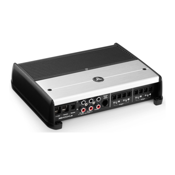
TURN-ON LEAD INPUT SECTION The XD400/4 uses a conventional +12V remote The XD400/4’s input section allows you to turn-on lead, typically controlled by the source send signals to the amplifier section through the unit's remote turn-on output. The amplifier will use of two or four differential-balanced inputs. -
Page 7: Input Sensitivity Controls
INPUT SENSITIVITY CONTROLS The controls labeled “Input Sens.” located in each channel section can be used to match the source unit’s output voltage to the input stage of each pair of amplifier channels for maximum clean output. Rotating the control clockwise will result in higher sensitivity (louder for a given input voltage). -
Page 8: Filter Controls
FILTER CONTROLS Most speakers are not designed to reproduce types or defeated completely by way of the the full range of frequencies audible by the human three-position “Filter Mode” switches: ear. For this reason, most speaker systems are “Off”: Defeats the filter completely, allowing comprised of multiple speakers, each dedicated the full range of frequencies present at the to reproducing a specific frequency range. -
Page 9: Remote Level Control (Optional)
REMOTE LEVEL CONTROL (OPTIONAL) PREOUTS The XD400/4 incorporates a pass-through preamp output section, so that additional amplifiers can be easily added to the system. This pass-through pre-amp output can be configured two different ways using the switch labeled “Preouts From”. 1) “1&2”: The preamp output delivers the same With the addition of the optional Remote signal that is connected to the CH 1&2 Inputs. -
Page 10: Speaker Outputs
SPEAKER OUTPUTS “Left –” and “Right +” remain unused). When The XD400/4’s speaker outputs are designed bridged, each channel will deliver optimum to accept 16 AWG - 8 AWG wire. To connect the power into a 4 ohm load. speaker wires to the amplifier, first back out the set screws on the top of the terminal block, using the supplied 2.5 mm hex wrench. -
Page 11: Status Led / Protection Circuitry
STATUS LED / PROTECTION CIRCUITRY There is a single multi-color LED on the top 5) LED off / Amplifier Shuts Off Unexpectedly surface of the amplifier to indicate the amplifier’s The only condition that will shut down operating status. an undamaged XD400/4 completely is if battery voltage or remote turn-on voltage drops below 10 volts. -
Page 12: System Configurations
SYSTEM CONFIGURATIONS The XD400/4 is a flexible amplifier, well- Inp ut Connections: the first stereo pair of source suited for a multitude of system configurations. unit outputs is connected to the “CH 1 (Left)” In this section, the most likely configurations for and “CH 2 (Right)”... -
Page 13: Multi-Amplifier Systems
14), you can fine tune filter frequencies and B) Subwoofer Level Control Only: attenuate either pair of channels to achieve Req uired: a source unit or processor with left, proper balance. For precise filter frequency right and dedicated subwoofer outputs. information refer to Appendix B (page 15). - Page 14 APPENDIX A: Input Sensitivity Level Setting 9) Once you have adjusted the XD400/4 to Following the directions below will allow the its maximum low-distortion output level, installer to adjust the input sensitivity of each reconnect the speaker(s). The “Input Sens.” amplifier channel pair simply and easily in just a controls can now be adjusted downward if the few minutes using equipment which is commonly...
- Page 15 08 ... “60” ... .57 Amplifier Topology: NexD™ Ultra-High Speed Class D 09 ......59 Power Supply: Unregulated MOSFET switching type 10 .
-
Page 16: Appendix D: Troubleshooting
APPENDIX D: TROUBLESHOOTING “How do I properly set the input sensitivity on my amplifier?” Please refer to Appendix A (page 14) to set the input sensitivity for maximum, low-distortion output. “My amplifier doesn’t turn on.” Check the fuse, not just visually, but with a continuity meter. It is possible for a fuse to have poor internal connections that cannot be found by visual inspection. - Page 17 “My amplifier shuts off once in a while, usually at higher volumes.” Check your voltage source and grounding point. The power supply of the XD400/4 will operate with charging system voltages down to 10V. Shutdown problems at higher volume levels can occur when the charging system voltage (or remote turn- on voltage) momentarily drops below 10V.
-
Page 18: Installation Notes
INSTALLATION NOTES: Use this diagram to document your amplifier’s switch and control positions. 18 | JL Audio - XD400/4 Owner’s Manual... - Page 20 LIMITED WARRANTY - AMPLIFIERS (USA) JL AUDIO warrants this product to be free of defects in materials and workmanship for a period of two (2) years. The warranty is extended to three (3) years total if installation is performed by an authorized JL Audio dealer using a JL Audio Premium Power Connection System for power wiring.
- Page 21 w w w . j l a u d i o . c o m Printed in China XD400/4 MAN-02-2010...