
Related Manuals for Daikin DCS302C51


Summary of Contents for Daikin DCS302C51
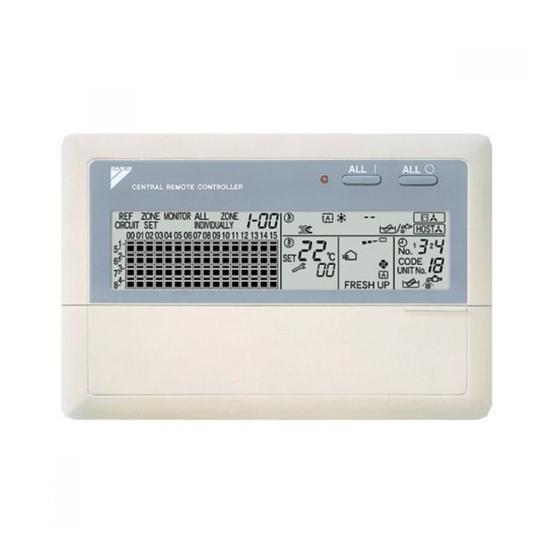
- Page 1 OPERATION MANUAL CENTRAL REMOTE CONTROLLER MODELS English DCS302C51 Deutsch Français Español Italiano ΕλληνικÜ Nederlands Portugues...
- Page 2 Read these instructions carefully before installation. Keep this manual in a handy place for future reference. This manual should be left with the equipment owner. Lesen Sie diese Anleitungen vor der Installation sorgfältig durch. Bewahren Sie dieses Handbuch zum späteren Nachschlagen auf. Dieses Handbuch sollte immer im Besitz des Geräteeigentümers verbleiben.
- Page 3 ( 4 ) ( 5 ) ( 6 ) ( 7 ) (10) ( 9 ) ( 3 ) ( 1 ) (11) ( 2 ) (12) (13) OPTION INDIVIDUALLY (14) TEST (20) CODE (21) UNIT No. H HH AVAILABLE FRESH UP ( 8 ) (16) (17)
- Page 4 INDIVIDUALLY INDIVIDUALLY...
-
Page 5: Before Use
BEFORE USE GENERAL DESCRIPTION OF SYSTEM This central remote controller can monitor and control up to 64 indoor unit groups. Using two central remote controllers allows monitoring and controlling of up to 128 indoor unit groups. Main Functions Batch starting and stopping of indoor units connected to the central remote controller. Handling of operation settings such as start/stop, timer operation, remote controller prohibition/permission, etc., and operation status settings such as temperature. -
Page 6: Safety Considerations
Be sure only unit operates properly during the start-up operation. to use accessories made by Daikin which are specifically Please instruct the customer on how to operate the unit designed for use with the equipment and have them and keep it maintained. -
Page 7: Table Of Contents
Do not turn off the power immediately after stop- CAUTION ping operation. Always wait at least five minutes before turning off the After a long use, check the unit stand and fitting power. Otherwise, water leakage and trouble may occur. for damage. -
Page 8: Features And Functions
FEATURES AND FUNCTIONS n Operation menu This central remote controller can operate and stop machines by See page either group or zone. 6—10. Batch operation and batch stop functions are also available. When used in combination with the schedule timer (optional accessory), timer operation and stop functions are available. -
Page 9: Names And Functions Of The Operating Section
NAMES AND FUNCTIONS OF THE OPERATING SECTION (Fig. 1, 2) UNIFIED OPERATION BUTTON “ ” DISPLAY (COOLING/HEATING SELECTION PRIVILEGE NOT SHOWN) Press to operate all indoor units. UNIFIED STOP BUTTON For zones or individual units (groups) for which this is displayed, cooling and heating cannot be Press to stop all indoor units. -
Page 10: Operation
SET BUTTON CODE “ ” DISPLAY (OPERATION UNIT No. Sets control mode and time No. CODE AND UNIT NUMBER DISPLAY) FAN STRENGTH ADJUSTMENT The method of operation (remote controller BUTTON prohibited, central operation priority after-press operation priority, etc.) is displayed by the Pressing this button scrolls through “weak”, corresponding code. -
Page 11: Batch Operation And Stop Method
• If the zone number in the zone screen is dis- Group operation and stop method played as “---,” this indicates that no units are (Fig. 5) registered in a zone. This is for operating or stopping connected units in Please perform zone registration before pro- groups. -
Page 12: Zone Operation And Stop Method
[Batch deletion of zone registration] Select the Zone Number to be regis- tered using the “ZONE NUMBER” button. Pressing the “ ” for at least Keeping the button pressed down will move it four seconds while pressing the “FIL- rapidly. TER SIGN RESET”... -
Page 13: Changing The Fan Direction And Fan Strength
Changing the fan direction and fan Press the “VENTILATION MODE” strength (Fig. 8) button. This changes the fan direction and strength settings in ” → “ ” → “ It will scroll through “ ” the air conditioner. → “ ”. -
Page 14: Setting The Operation Code
When using timer operation, make sure the Select the desired timer number by times do not overlap when setting the program of pressing the “TIMER NO.” button. the schedule timer. Once the desired timer number is displayed, press the “SET” Setting the Operation Code (Fig. -
Page 15: Operation Mode
OPERATION MODE The following five operation control modes can be selected along with the temperature setting and operation mode by remote controller, for a total of twenty different modes. These twenty modes are set and displayed with control modes of 0 to 19. (For further details, see EXAMPLE OF OPERATION SCHEDULE on the next page.) •... - Page 16 Control by remote controller Operation Operation Control Unified operation, individ- Unified stop, individual Tempera- Operation mode mode Stop ual operation by central stop by central remote ture control mode setting remote controller, or opera- controller, or timer tion controlled by timer stop Acceptance Rejection...
- Page 17 Only OFF control possible by remote controller Operation Timer stops even Operation controlled by if you forget to SET1 controlled Centralized timer turn off the unit. by timer Programmed to Programmed to Programmed to - - - Stop SET2 - - - stop at 5:00 operate at 5:20 operate at 8:45...
-
Page 18: Setting Operation Mode
∗1: Setting may not be acceptable depending on the Setting operation mode (Fig. 12) type of indoor unit with which this unit is connected. ∗2: In zone control, the units run in temperature adjust- [Registration] ment mode (heating or cooling) for the outdoor sys- Press the OPERATION MODE SELEC- tem for the groups registered to those zones. -
Page 19: Error Diagnosing Function
Check the contents of the display, The zone screen will revert to the individual screen and contact your DAIKIN dealer because the above automatically if nothing is done in it for one minute. signs can give you the idea on the trouble area. - Page 20 Indoor unit · Liquid piping thermistor (Th2) Error (faulty connec- tion, cut wire, short circuit, fault) Indoor unit · BEV unit, gas piping thermistor (Th3) Error (faulty connection, cut wire, short circuit, fault) Indoor unit · Intake air thermistor (Th1) Error (faulty connection, cut wire, short circuit, fault) Indoor unit ·...
- Page 21 Outdoor unit · Ground circuit for compressor motor, short circuit Outdoor unit · Compressor overload, compressor motor wire disconnection Outdoor unit · Compressor lock Outdoor unit · Power unit error Outdoor unit · Transmission error between inverter and outdoor control unit Central controller: PC board fault Transmission error between central controllers Central controller: Incorrect combination...
-
Page 22: Setting Master Remote Controller
Setting master remote controller When switching operation ● ● ● ● In case of operation switch (Fig. 15) Call up the zone including the group with the You must set the master remote controller of the oper- ation mode for one of the indoor units, if two or more setting of master remote controller. -
Page 23: Display Of Time To Clean
Call the unit whose system you wish to look up using Press the FILTER SIGN RESET BUT- the arrow keys. TON, and the display “ ” disap- The “ ” on all groups in the same system as the pears. (Including all the groups where the displayed group will light up. -
Page 24: Installation Table
INSTALLATION TABLE When installing the equipment, mark the zone No. of each group and installation location in the below table. Setting group No. Operated by simplified remote controller (Setting is not possible unless power is activated to 1. Activate power to both the central remote controller both the central remote controller and indoor unit.) and indoor unit. -
Page 25: Optional Accessories
You can perform the normal operation, take off the malfunction contact point and unified start/stop by contact point, all by connecting this unit with the unification adaptor for computerized control. For further details, ask your DAIKIN dealer. (a) Unification adaptor for computerized control... -
Page 26: Specifications
SPECIFICATIONS Specifications Power supply 1 ~ 50/60Hz, 100V – 240V Power consumption Max. 8W Continuous “a” contact Forced ON/OFF input Contact current: approximately 10mA Size 180 (W) × 120 (H) × 64.5 (D) Weight 420g Outline drawings 48.5 INDIVIDU INDIVIDUALL ALLY When using this unit an electric parts box of KJB311A is required. - Page 27 INDIVIDUALLY FRESH UP INDIVIDUALLY INDIVIDUALLY CODE INDIVIDUALLY...
- Page 28 INDIVIDUALLY Operation lamp INDIVIDUALLY UNIT No. INDIVIDUALLY INDIVIDUALLY...
- Page 29 3P124623-2A EM03A107 (0401) HT...