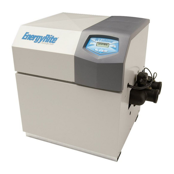
Lochinvar EnergyRite ER202 Installation & Operation Manual
Hide thumbs
Also See for EnergyRite ER202:
- Installation & operation manual (52 pages) ,
- Service manual (32 pages) ,
- User's information manual (12 pages)
Table of Contents
Advertisement
Quick Links
ERP-I-O_100161007_2000003722_Rev L
Installation & Operation
Manual
Models: ER152, ER202, ER252,
ER302, and ER402
⚠ WARNING:
This manual supplies information for the
installation, operation, and servicing of the
appliance. It is strongly recommended that this
manual and the EnergyRite Service Manual be
reviewed completely before proceeding with an
installation. Perform steps in the order given.
Failure to comply could result in severe personal
injury, death, or substantial property damage.
Save this manual for future reference.
Advertisement
Table of Contents

Related Manuals for Lochinvar EnergyRite ER202


Summary of Contents for Lochinvar EnergyRite ER202
- Page 1 ERP-I-O_100161007_2000003722_Rev L Installation & Operation Manual Models: ER152, ER202, ER252, ER302, and ER402 ⚠ WARNING: This manual supplies information for the installation, operation, and servicing of the appliance. It is strongly recommended that this manual and the EnergyRite Service Manual be reviewed completely before proceeding with an installation.
-
Page 2: Table Of Contents
Installation & Operation Manual Contents Hazard definitions ....................2 Please read before proceeding ................3 Ratings ........................5 The EnergyRite -- How it works ................6 Determine pool heater location ................ 8 General venting ....................12 Conventional venting ..................17 Vertical venting .................... -
Page 3: Please Read Before Proceeding
Installation & Operation Manual Please read before proceeding Improper installation, adjustment, alteration, This is a gas appliance and should be NOTICE ⚠WARNING service or maintenance can cause injury or installed by a licensed electrician and/or property damage. Refer to this manual for certified gas supplier. - Page 4 Installation & Operation Manual Please read before proceeding Spa and hot tub safety – Codes – The following safety rules must be observed while operating This pool heater has been designed and certified under spa or hot tub. the latest edition of Z21.56/CSA 4.7 Gas Fired Pool Heater Standard, including applicable addenda.
-
Page 5: Ratings
Installation & Operation Manual Ratings Model Number Input Pool Heater Water Content Connections Vent/Air Size Maximum Working Pressure Btu/hr Gallons Note: Change “N” to (PSI) “L” for Propane gas models. DirectAire E-Rite (Note 3) Add suffix “-A” for (NPT) ASME NON-ASME Conventional ASME... -
Page 6: The Energyrite - How It Works
Installation & Operation Manual The EnergyRite - How it works... Heat exchanger 16. Flame inspection window Allows pool water to flow through specially designed The quartz glass window provides a view of the burner tubes for maximum heat transfer, while providing protection surface and flame. - Page 7 Installation & Operation Manual The EnergyRite - How it works... (continued) Models ER152 - ER402 Rear View Front View IMG00957 Right Side (inside unit) Left Side (inside unit)
-
Page 8: Determine Pool Heater Location
Installation & Operation Manual Determine pool heater location Location of pool heater 7. Indoor installations require that the factory installed outdoor 1. Locate the pool heater so that if water connections should vent cap be removed from the pool heater to allow the leak, it will not result in damage to the area adjacent to installation of a flue pipe. - Page 9 Installation & Operation Manual Determine pool heater location (continued) Combustion ventilation TABLE - 1A requirements conventionally CLEARANCES FROM COMBUSTIBLE CONSTRUCTION vented appliances and sidewall Location Clearances vented appliances Right Side 3" (24" suggested for service) Provisions for combustion and ventilation air must Rear (Outdoor) 3"...
- Page 10 Installation & Operation Manual Determine pool heater location Figure 1-5_Combustion Air from Outside - Single Figure 1-3_Combustion Air Through Ducts Opening If a single combustion air opening is provided to bring If combustion and ventilation air is taken from the combustion air in directly from the outdoors, the outdoors using a duct to deliver the air to the equipment opening must be sized based on a minimum free area...
- Page 11 Installation & Operation Manual Determine pool heater location (continued) TABLE - 1B MINIMUM RECOMMENDED COMBUSTION AIR SUPPLY TO EQUIPMENT ROOM Outside Air from Inside Air from Inside Air from 2 Openings Directly from 2 Ducts Delivered from 2 Ducts Delivered from Outside Air from Model Outdoors...
-
Page 12: General Venting
Installation & Operation Manual General venting Vent system options Figure 2-1_Conventional Negative Draft Venting - Figure 2-2_DirectAire Vertical w/Sidewall Air Inlet - See page 17 for more details See page 21 for more details Figure 2-3_DirectAire Vertical Venting w/Vertical Figure 2-4_Power Sidewall Venting - See page 24 for Air Inlet - See page 20 for more details more details... - Page 13 Installation & Operation Manual General venting (continued) Figure 2-5_Power DirectAire Horizontal Venting - See Figure 2-6_E-Rite Sidewall Venting - See page 27 for more details page 25 for more details This pool heater has six (6) venting options. They are: (1) Conventional Negative Draft Venting with vertical rooftop flue termination and combustion air supplied from the equipment room, (2) DirectAire Vertical Venting with a...
- Page 14 Installation & Operation Manual General venting Outdoor installation General Units are self venting and can be used outdoors when installed Vent installations for connection to gas vents or chimneys with the factory supplied outdoor vent cap. The outdoor must be in accordance with “Venting of Equipment”, of the vent cap is mounted directly to the rear of the pool heater as latest edition of the National Fuel Gas Code, ANSI Z223.1, in shipped from the manufacturer and covers the flue outlet and...
- Page 15 Installation & Operation Manual General venting (continued) The outdoor pool heater must not be installed in an area that is enclosed by walls or a fence that will block free wind movement around the pool heater. Free movement of wind around the outdoor unit is required to carry away the flue products and provide combustion air.
- Page 16 Installation & Operation Manual General venting An Outdoor Installation, DirectAire Vent or ⚠WARNING AIR INLET an E-Rite Vent into dead air spaces such as COVER alleys, atriums, and inside corners can cause recirculation of flue gases. Recirculation of flue gases will cause incomplete combustion, sooting, premature failure of the jacket, vent and heat exchanger as well as icing of the combustion air intake during operation in...
-
Page 17: Conventional Venting
Installation & Operation Manual Conventional venting A conventional negative draft venting system The negative draft in a conventional vent installation must be within the range of a negative 0.02 to 0.08 inches water to ensure proper operation. All draft readings are made while the unit is in stable operation (approximately 2 to 5 minutes). - Page 18 Installation & Operation Manual Conventional venting Common venting systems may be too large when an existing unit is removed. At the time of removal of an existing appliance, the steps below shall be followed with each appliance remaining connected to the common venting system placed in operation, while other appliances remaining connected to the common venting system are not in operation.
-
Page 19: Vertical Venting
Installation & Operation Manual Vertical venting Vertical venting termination Figure 4-1_Vent Termination from Peaked Roof - Figure 4-2_Vent Termination from Flat Roof 10 Feet 10 Feet or Less From Ridge or Less from Parapet Wall Figure 4-4_Vent Termination from Flat Roof More Figure 4-3_Vent Termination from Peaked Roof Than 10 Feet from Parapet Wall More Than 10 Feet From Ridge... - Page 20 Installation & Operation Manual Vertical venting The directaire vertical vent system The venting system shall terminate at least 4 feet below, 4 feet horizontally from, or 1 foot above any door, window, or gravity A vertical negative draft venting system air inlet into any building.
- Page 21 Installation & Operation Manual Vertical venting (continued) Figure 4-7_DirectAire Vertical Installation with Figure 4-5_DirectAire Vertical with Sidewall Venting Rooftop Combustion Air Sidewall air inlet Vertical rooftop air inlet The sidewall air inlet cap kit is supplied as one of the The air inlet arrangement as shown in FIG.
- Page 22 Installation & Operation Manual Vertical venting Incorrect installation and/or location of the air inlet opening The air inlet pipe(s) must be sealed. Choose acceptable can allow the discharge of flue products to be drawn into combustion air inlet pipe materials from the following specified the combustion process on the pool heater.
- Page 23 Installation & Operation Manual Vertical venting (continued) Pool heaters which are shut down TABLE - 4A ⚠ CAUTION or will not operate may experience DIRECTAIRE VENT KITS freezing due to convective air flow DirectAire DirectAire Model Conventional Air Inlet in the air inlet pipe connected to the w/rooftop w/sidewall Number...
-
Page 24: Sidewall Venting
Installation & Operation Manual Sidewall venting The power sidewall venting system Length of flue pipe Power sidewall venting with combustion air The maximum total equivalent length of flue pipe connected from the equipment room to the power sidewall cap cannot exceed 75 equivalent feet. Subtract 5 feet for each elbow in the vent. - Page 25 Installation & Operation Manual Sidewall venting (continued) Venting of flue products Pool heaters which are shut down or will ⚠ CAUTION not operate may experience freezing due to The sidewall vent cap shall terminate at least 3 feet above convective air flow into the equipment room. any forced air inlet within 10 feet.
- Page 26 Installation & Operation Manual Sidewall venting The Power DirectAire Horizontal combustion air supply system Use care to ensure that the air inlet cap assembly is properly has specific material and installation requirements. The air installed on the air inlet pipe. The combustion air inlet cap and inlet pipe uses an adapter to supply combustion air and for the power vent cap MUST be installed on the same wall and the connection directly to the pool heater.
- Page 27 Installation & Operation Manual Sidewall venting (continued) E-Rite sidewall venting system TABLE - 5B POWER DIRECTAIRE HORIZONTAL VENT KITS Model DirectAire Power DirectAire Flue Size Number Inlet Pipe* Horizontal Kit ER152 4" 4" 100169242 ER202 4" 4" 100169242 ER252 5" 5"...
- Page 28 Installation & Operation Manual Sidewall venting The E-Rite Sidewall Vent kit includes recommendations to TABLE - 5C purchase and install specific sidewall vent terminations from AIR SHUTTER ADJUSTMENT OPENING FOR recommended AL29-4C vent system manufacturers. This E-RITE VENT SYSTEMS venting kit includes installation instructions, a flue adapter, Model “A”...
- Page 29 Installation & Operation Manual Sidewall venting (continued) Sealing of venting materials Length of flue pipe and air inlet pipe for an e-rite sidewall vent system The AL29-4C vent materials must be installed and sealed per the vent manufacturer’s installation instructions. The maximum total equivalent length of the flue or the combustion air inlet pipe must not exceed a maximum of 20 The E-Rite Sidewall Vent System requires installation of...
- Page 30 Installation & Operation Manual Sidewall venting E-Rite sidewall vent termination When an E-Rite Sidewall Vent System is disconnected for any reason, the flue must be reassembled and resealed according The sidewall vent cap shall terminate at least 3 feet above any to the vent manufacturer’s instructions to ensure that flue forced air inlet within 10 feet.
- Page 31 Installation & Operation Manual Sidewall venting (continued) The combustion air inlet caps for multiple unit installations must maintain the minimum 3 foot radius clearance below or horizontally from the closest flue outlet. Multiple flue outlet caps may be installed side by side and multiple air inlet caps may be installed side by side but the 3 foot radius minimum clearance between air inlet and flue outlet must be maintained.
-
Page 32: Gas Connections
Installation & Operation Manual Gas connections Gas supply Gas connection Verify unit is supplied with the type of gas specified on the Safe operation of the unit requires properly sized gas supply rating plate. This unit is orificed for operation up to 4000 piping. - Page 33 Installation & Operation Manual Gas connections (continued) Install piping to gas valve LP gas installations LP (propane) gas is heavier than air and The gas line should be a separate line direct from the meter ⚠ WARNING will remain at floor level if there is a unless the existing gas line is of sufficient capacity.
-
Page 34: Water Connections
Installation & Operation Manual Water connections This pool heater is equipped with an automatic, built-in bypass located in the front header. This bypass is flow actuated to maintain proper flow through the pool heater at flow rates of less than 100 GPM. If the water flow rate to the pool heater exceeds 100 GPM, an auxiliary bypass must be installed in the piping to the pool heater. - Page 35 Installation & Operation Manual Water connections (continued) Water chemistry We recommend a periodic analysis be performed to maintain and ensure proper operation of your pool heater (see Table 7B). TABLE 7B RECOMMENDED POOL CHEMISTRY LEVELS Test Recommended Level Bromine 2.0 - 4.0 ppm Calcium Hardness 200 - 400 ppm Cyanuric Acid...
-
Page 36: Electrical Connections
Installation & Operation Manual Electrical connections Terminal strip for third party remote or This appliance is wired for 240 VAC service. The pool heater proving switch can be converted to 120 VAC by moving the jumper connector from the connector labeled 240 VAC to the connector labeled 2-Wire Remote: 120 VAC as shown in FIG. - Page 37 Installation & Operation Manual Electrical connections (continued) High water temperature limit controls Integrated controller The pool heater is equipped with a microprocessor based The pool heater is equipped with one auto-reset high water adjustable digital integrated controller to provide ON/ temperature limit control.
-
Page 38: Start-Up
Installation & Operation Manual Start-up... - Page 39 Installation & Operation Manual Start-up (continued) Energy saving recommendations Keep the pool/spa covered when not in use. This will cut heating cost, reduce water evaporation, conserve chemicals and reduce load on the filtering system. Reduce pool thermostat to 78°F (25°C) or lower, reduce spa temperature to 100°F (38°C).
- Page 40 Installation & Operation Manual Start-up Turn on gas supply at the manual gas cock, turn on LP Upon completion of any testing on the gas NOTICE gas at tank if required. system, leak test all gas connections with a soap and water solution while main burners Turn the power switch to the “ON”...
-
Page 41: Operating Information
Installation & Operation Manual Operating information General Protection features How the pool heater operates High limit A high limit device is used to monitor the water temperature at The EnergyRite uses a copper finned tube heat exchanger the discharge of the heat exchanger. If the water temperature and an electronic control module. - Page 42 Installation & Operation Manual Operating information Auxiliary safety 1 and 2 Two auxiliary safeties may be connected to the control module. The control module will not initiate or will terminate a call for heat if either safety is open. The control module will show AUXILIARY SAFETY 1 OPEN or AUXILIARY 2 OPEN in the display.
- Page 43 Installation & Operation Manual Operating information (continued) Sequence of operation OPERATION DISPLAY 1. Upon a call for heat, the control module will look at the POOL: Standby high limit, the water pressure switch, and the auxiliary safeties. If any of these devices are open, the control POOL TEMP: 78°F module will not initiate an ignition sequence.
- Page 44 Installation & Operation Manual Operating information EnergyRite control module Use the control panel (FIG. 10-1) to set temperatures, operating conditions, and monitor unit operation. Figure 10-1_ Control Panel POOL/SPA/OFF RESET/MENU POOL/SPA/OFF RESET/MENU (Press to Exit Menu/Settings) (Hold for Menu/Settings) SWIPE BUTTONS ALONG ARROWS TO UNLOCK *WAIT 5 SECONDS...
- Page 45 Installation & Operation Manual Operating information (continued) Access modes Setup menu Modes of operation Additional features can be accessed and adjusted through the There are three modes of operation: 1) Off, 2) Pool, and Setup Menu. Please reference the EnergyRite Service Manual 3) Spa.
-
Page 46: Wiring Diagram
Installation & Operation Manual Operating information Figure 10-2_Wiring Diagram... -
Page 47: Ladder Diagram
Installation & Operation Manual Operating information (continued) Figure 10-3_Ladder Diagram NOTES: L2/N 1. Where possible, switches are shown without utilities (gas, water or electricity) connected to the unit. As such, actual switch states may vary from those shown on diagrams depending upon whether utilities are connected or a fault condition is present. -
Page 48: Asme Addendum
Installation & Operation Manual ASME addendum The EnergyRite - How it works... Heat exchanger Allows pool water to flow through specially designed tubes for maximum heat transfer, while providing protection against flue gas corrosion. Outlet temperature sensor This sensor monitors outlet water temperature and will shut down the unit if this temperature gets too high. Inlet temperature sensor This sensor monitors the inlet water temperature and will be used by the integrated control to determine whether an ignition cycle should begin. -
Page 49: Water Connections
Installation & Operation Manual ASME addendum (continued) Water connections Inlet and outlet connections Connection to the pool heater can be made with either 2" threaded pipe or a slip connection with 1 1/2" or 2" pipe. Two inch threaded pipe may be directly screwed into the flanged header connections for both inlet and outlet piping. -
Page 50: Relief Valve
Installation & Operation Manual ASME addendum Relief valve Adjustment of auxiliary bypass Backwash and clean pool filters. A pressure relief valve is installed in the vertical position and mounted in the front header on the hot water outlet of the pool Start with the bypass valve in the half open position. - Page 51 NOTES...
- Page 52 Revision Notes: Rev. B (ERP-I&O-Rev. B) reflects changes made to font on Page 24 and to Figure 10-2. Revision C (ECO C02053) reflects edits made to the E-Rite Sidewall Venting Section on Page 27. Revision D (ECO C04538) reflects the addition of salt levels to the Caution on Page 35.