Table of Contents
Advertisement
Quick Links
OPERATING AND
INSTALLATION
INSTRUCTIONS
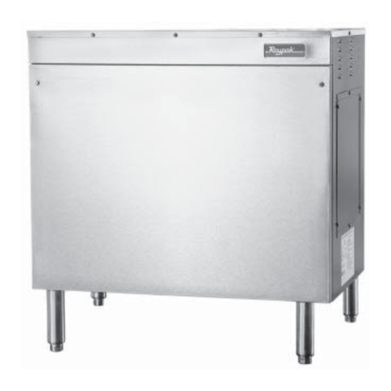
Model B-195
GAS FIRED AUTOMATIC
INSTANTANEOUS
BOOSTER WATER
HEATER
FOR YOUR SAFETY
Do not store or use gasoline or other flammable vapors and liquids or other combustible
materials in the vicinity of this or any other appliance. To do so may result in an explosion
or fire.
WARNING: Improper installation, adjustment, alteration, service or maintenance can cause
property damage, personal injury or loss of life. Refer to this manual. Installation and service
must be performed by a qualified installer, service agency or the gas supplier.
FOR YOUR SAFETY
WHAT TO DO IF YOU SMELL GAS
*Do not try to light any appliance.
*Do not touch any electrical switch; do not use any phone in your building.
*Immediately call your gas supplier from a neighbor's phone. Follow the gas supplier's
instructions.
*If you cannot reach your gas supplier, call the fire department.
This manual should be maintained in legible
condition and kept adjacent to the heater or kept
in a safe place for future reference.
Product Discontinued December 2003
CATALOG NO.: 3300.51I
Effective:
01-01-03
Replaces: 01-01-01
NSF
®
P/N 240707
Advertisement
Table of Contents

Related Manuals for Rheem Raypak B-195


Summary of Contents for Rheem Raypak B-195
- Page 1 CATALOG NO.: 3300.51I Effective: 01-01-03 Replaces: 01-01-01 OPERATING AND INSTALLATION INSTRUCTIONS Model B-195 GAS FIRED AUTOMATIC INSTANTANEOUS BOOSTER WATER HEATER FOR YOUR SAFETY Do not store or use gasoline or other flammable vapors and liquids or other combustible materials in the vicinity of this or any other appliance. To do so may result in an explosion or fire.
-
Page 2: Table Of Contents
CONTENTS PAGE DESCRIPTION RECEIVING EQUIPMENT GENERAL SPECIFICATIONS AND DIMENSIONS INSTALLATION PROCEDURES - Code Requirements - Combustion/Ventilation Air - Venting - Gas Piping - Water Piping - Electrical Wiring START-UP AND OPERATION - Component Location - Sequence of Operation - START-UP Procedures. SERVICING UNIT - Trouble Shooting Guide - Maintenance... -
Page 3: 1. Receiving Equipment
1. RECEIVING EQUIPMENT On receipt of your equipment it is suggested that you visually check for external damage to the carton. If the carton is damaged, it is suggested that a note be made on the Bill of Lading when signing for equipment. Remove the heater from the carton and if it is damaged report the damage to the carrier immediately. -
Page 4: 3. Installation Procedures
3. INSTALLATION PROCEDURES. CODE REQUIREMENTS Installation must be in accordance with local codes, or in the absence of local codes with the latest edition of the National Fuel Gas Code, ANSI Z223.1, the National Electrical Code, ANSI/NFPA 70. For Canada, CAN/ CGA B149.1 and .2, and CSA C22.2 No. -
Page 5: Venting
Measures must be taken to prevent the entry of corrosive chemical fumes to the combustion and ventilation air supply. Such chemicals include, but are not limited to, chlorinated and/or fluorinated hydrocarbons such as found in refrigerants, aerosol propellants, dry-cleaning fluids, degreasers, and paint removers. Other harmful elements may come from bleaches, air fresheners, or mastics. - Page 6 equipment. Applies only to exhaust hood over cooking Fig. #8975.3...
- Page 7 All horizontal runs of the vent pipe shall have a The gas booster heater may be vented 3 ways: minimum rise of 1/4" per foot of length and should be supported at maximum intervals of 5 feet (for Canada, 1. Through the sidewall, or the ceiling, as discussed 3 feet) and at each point where an elbow is used.
-
Page 8: Gas Piping
GAS PIPING The gas inlet pipe size is 1/2" NPT to the gas valve. Provide an adequate size gas supply line. The line should not be smaller than 1/2" NPT according to the chart below. MAXIMUM EQUIVALENT PIPE LENGTH (FEET) Pipe Size 1/2"... - Page 9 A drain valve is provided in the tank for draining water during servicing. The temperature and pressure relief valve is easily accessible through the front. A nipple is provided (shipped loose with the heater) for installation in the T & P relief valve. A drain line must be connected to the nipple and run to a safe place of disposal.
- Page 10 ELECTRICAL The electrical power supply requirement for the heater is 120 volts, 60 Hz, 5.0 amps or less . Field wiring connections and electrical grounding must comply with the local codes, or in the absence of local codes, with the latest edition of the National Electrical Code, ANSI/NFPA 70. NOTE: Polarity must be observed for the heater to operate properly.
- Page 11 LADDER DIAGRAM CONNECTION DIAGRAM DANGER: SHOCK HAZARD Turn off electrical power to boost heater before servicing any component in the heater to prevent equipment damage or personal injury. NOTE: If it is necessary to replace any of the original wiring, it must be replaced with 105°C rated wire or its equivalent.
-
Page 12: Start-Up And Operation
4. START UP AND OPERATION COMPONENT LOCATION SEQUENCE OF OPERATION off until the next call for heat. The operating limit control The booster heater is designed to maintain a tempera- is factory set at 185°F. Combustion air blower and the ture of 180 deg. - Page 13 SECTION 3. LIGHTING THE HEATER 4. This appliance is equipped with an ignition device which automatically lights the burners. Do Safety lighting and other performance criteria were not try to light the burners by hand. met for the burner assembly and control assembly 5.
- Page 14 SECTION 4. 3. Remove screws on burner access panel. TESTING THE IGNITION SAFETY SHUT-OFF 4. Remove refractory block. 5. Visaully inspect burner tray panel. The ignition system safety shut-off must be tested by 6. Reverse above procedure to reinstall, checking conducting the following method of tests: burner tray and seal to prevent leakage.
- Page 15 5. Limit Control Module 11. Combustion Air Blower Replacement a) Shut-off electrical power to the heater. a) Shut off electrical power to heater. b) Remove control cover screws and open con- b) Remove front panel and access cover on left trol compartment.
-
Page 16: Servicing Unit
5. SERVICING UNIT TROUBLE SHOOTING GUIDE POSSIBLE CAUSE SUGGESTED SOLUTION PROBLEM 1. On-Off switch energized. Unit 1a. No power to heater a. Cycle the Power Switch off then on. -Check circuit breaker and electrical does not operate. disconnect. -Check for reversed polarity and im- proper ground. - Page 17 Continuation TROUBLE SHOOTING GUIDE 3d. Excessive vent exhaust or 3d. Excessive negative pressure exerted defective air/vent switch. by the exhaust system on the vent will prevent N.O. combustion air/vent switch from closing. Provide means to relieve pressure and close the N.O. switch.
-
Page 18: Parts List
6. REPLACEMENT PARTS LIST NOTE: To supply the correct part it is important that you state the model number, serial number and type of gas when applicable. Any part returned for replacement under standard company warranties must be properly tagged with RAYPAK return parts tag, completely filled in with the heater Serial Number, Model Number etc., and shipped to the Company freight prepaid. -
Page 22: Warranty
LIMITED PARTS WARRANTY COMMERCIAL BOOSTER HEATER SCOPE: Raypak, Inc. ("Raypak") warrants to the owner that all parts of this booster heater, excluding controls and pump, will be free from failure under normal use and service for the specified warranty periods and subject to the conditions set forth in this Warranty. - Page 23 www.raypak.com Raypak, Inc., 2151 Eastman Avenue, Westlake Village, CA 93030 (805) 278-5300 FAX (800) 872-9725 Raypak Canada Limited, 2805 Slough St., Mississauga, Ontario, Canada L4T 1G2 (416) 677-7999 FAX (416) 677-8036 Litho in U.S.A.