Table of Contents
Advertisement
Quick Links
NEW Product
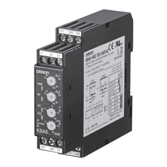
Single-phase Overcurrent/Undercurrent Relay
K8AK-AW
Ideal for Current Monitoring for
Industrial Facilities and Equipment.
• Monitor for overcurrents and undercurrents simultaneously.
Separate settings and outputs supported for overcurrents and
undercurrents.
• Use commercially available CTs (CT current on secondary
side: 0 to 1 A or 0 to 5 A).
• Manual resetting and automatically resetting supported by one
Relay.
• Startup lock and operating time can be set separately.
• Two sets of SPDT output contacts, 5 A at 250 VAC (resistive
load).
• Output status can be monitored using LED indicator.
• Inputs are isolated from the power supply.
Refer to Safety Precautions on page 12.
Refer to page 11 for commonly asked questions.
Ordering Information
List of Models
Setting range
Power supply voltage
2 to 20 mA AC/DC
24 VAC/DC
10 to 100 mA AC/DC
100 to 240 VAC
50 to 500 mA AC/DC
24 VAC/DC
0.1 to 1 A AC/DC
0.5 to 5 A AC/DC
100 to 240 VAC
24 VAC/DC
10 to 100 A AC*
20 to 200 A AC*
100 to 240 VAC
* The K8AK-AW3 is designed to be used in combination with an OMRON K8AC-CT200L Current Transformer (CT). (Direct input is not possible.)
Accessory (Order Separately)
●OMRON CT
Appearance
Input range
10 to 100 A AC,
20 to 200 A AC
Model
K8AK-AW1 24 VAC/DC
K8AK-AW1 100-240 VAC
K8AK-AW2 24 VAC/DC
K8AK-AW2 100-240 VAC
K8AK-AW3 24 VAC/DC
K8AK-AW3 100-240 VAC
Applicable
Model
Relay
K8AK-AW3
K8AC-CT200L
For the most recent information on models that have been certified for
safety standards, refer to your OMRON website.
●Commercially Available CTs*
Appearance
CT current on secondary side
0 to 1 A AC,
0 to 5 A AC
* If you use a commercially available CT, do not exceed the overload
capacity of the K8AK-AW2.
Applicable
Relay
K8AK-AW2
1
Advertisement
Table of Contents

Related Manuals for Omron K8AK-PH1 200/500VAC


Summary of Contents for Omron K8AK-PH1 200/500VAC
- Page 1 20 to 200 A AC* 100 to 240 VAC K8AK-AW3 100-240 VAC * The K8AK-AW3 is designed to be used in combination with an OMRON K8AC-CT200L Current Transformer (CT). (Direct input is not possible.) Accessory (Order Separately) ●OMRON CT ●Commercially Available CTs*...
- Page 2 1 s at 600% * CT capacity on primary side. *1 The range is selected using connected terminals. *2 The K8AK-AW3 is designed to be used in combination with an OMRON K8AC-CT200L Current Transformer (CT). (Direct input is not possible.)
- Page 3 Operating value setting range (SV) K8AK-AW2: 0.1 to 1 A AC/DC (Compatible with commercially available CTs.) 0.5 to 5 A AC/DC (Compatible with commercially available CTs.) K8AK-AW3: When used with the OMRON CT (K8AC-CT200L). 10 to 100 A AC 20 to 200 A AC...
-
Page 4: Specifications
K8AK-AW1 and K8AK-AW2: Continuous input at 120% of maximum input, 1 s at 150% Overload capacity K8AK-AW3: Continuous input at 120%, 30 s at 200%, and 1 s at 600% with an OMRON CT (K8AC-CT200L). Note: CT capacity on primary side. -
Page 5: Wiring Example
4. Refer to Setting Ranges and Wiring Connections on the I1, I2, and I3 current input terminals. 5. Use the recommended ferrules if you use twisted wires. 6. The K8AK-AW3 is designed to be used in combination with the OMRON K8AC-CT200L Current Transformer (CT). Wiring Example... - Page 6 • Use a timer for the K8AK undercurrent alarm (AL2) as a switch from contact “b” to contact “a” will not occur for approx. 250 ms even if the magnet contactor (RY2) is turned on. <Timer setting conditions (reference)> • TA : Timer (H3YN-2 + socket, Omron) • Operating mode : Interval mode • Setting time : 2 s Before pressing the startup button (after approx.
-
Page 7: Timing Charts
K8AK-AW Timing Charts • Always turn on the control power supply for K8AK at least 2 seconds before load startup. • Be aware that there is a power ON lock time (approx. 1 s) for the K8AK. • Output relays 11-14 and 21-24 will be conductive when the input level is normal. •... - Page 8 K8AK-AW ●Undercurrent and Undercurrent Operation Diagram (Undercurrent/Undercurrent Monitoring Mode) (When Using as an Undercurrent Pre-alarm) DIP switch settings: SW3 OFF and SW4 ON K8AK power supply voltage Hysteresis: Fixed at 5% Undercurrent set value (AL1) Hysteresis: Fixed at 5% Undercurrent set value (AL2) Flashing Flashing AL1 alarm indicator...
-
Page 9: Dip Switch Settings
Malfunctions may occur if the input is connected to unused terminals and the Unit will not operate correctly. K8AK-AW3 Terminal I1 is not used by the K8AK-AW3. If using the OMRON K8AC-CT200L CT, connect to terminals k and l on the K8AC-CT200L. (Terminals kt and lt are not used.) Power supply voltage ●Power Supply... - Page 10 81.5 33.5 30 dia. 14.5 14.5 Note: The OMRON Current Transformer (CT) is designed to be used with the K8AK-AW3. Use terminals k and l for connections. (Terminals kt and lt are not used.) Optional Parts for DIN Track Mounting ●DIN Tracks...
- Page 11 K8AK-AW Questions and Answers Can a motor with a rated current of 5 A be Checking Operation monitored using the K8AK? Are there any application precautions? Overcurrents The K8AK-AW1 and K8AK-AW2 cannot be used with motor Gradually increase the input from 80% of the set value. loads.
-
Page 12: Safety Precautions
K8AK-AW Safety Precautions Be sure to read the precautions for all models in the website at the following URL: http://www.ia.omron.com/. Warning Indications CAUTION Indicates a potentially hazardous situation CAUTION which, if not avoided, may result in minor or Electrical shock may cause minor injury. -
Page 13: Precautions For Safe Use
K8AK-AW Precautions for Safe Use Precautions for Correct Use 1. Do not use or store the product in the following locations. Observe the following operating • Locations subject to water or oil methods to prevent failure and • Outdoor locations or under direct sunlight malfunction. - Page 14 MEMO...
-
Page 15: Terms And Conditions Agreement
Data presented in Omron Company websites, catalogs and other materials is provided as a guide for the user in determining suitability and does not constitute a warranty. It may represent the result of Omron’s test conditions, and the user must correlate it to actual application requirements. - Page 16 Hoffman Estates, IL 60169 U.S.A. The Netherlands Tel: (31)2356-81-300/Fax: (31)2356-81-388 Tel: (1) 847-843-7900/Fax: (1) 847-843-7787 © OMRON Corporation 2014-2018 All Rights Reserved. OMRON (CHINA) CO., LTD. OMRON ASIA PACIFIC PTE. LTD. In the interest of product improvement, Room 2211, Bank of China Tower, No.