Table of Contents
Advertisement
Quick Links
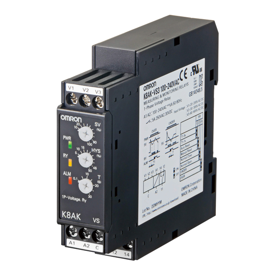
Single-phase Voltage Relay
K8AK-VS
Ideal for voltage monitoring for
industrial facilities and equipment.
• Monitor for overvoltages or undervoltages.
• Manual resetting and automatically resetting supported by one
Relay.
• One SPDT output relay, 5 A at 250 VAC (resistive load).
• Output relay can be switched between normally open and
normally closed.
• Process control signal (0 to 10 V) and current splitter input
supported.
• Output status can be monitored using LED indicator.
• Input frequency of 40 to 500 Hz supported.
• Inputs are isolated from the power supply.
Refer to Safety Precautions for the K8AK Series on page 86.
Refer to page 30 for commonly asked questions.
Ordering Information
List of Models
Control power supply
Setting range
1 to 10 V AC/DC
24 VAC/DC
3 to 30 V AC/DC
100 to 240 VAC
15 to 150 V AC/DC
20 to 200 V AC/DC
24 VAC/DC
30 to 300 V AC/DC
100 to 240 VAC
60 to 600 V AC/DC
Ratings and Specifications
Input Range
Model
Range*
0 to 10 V AC/DC
K8AK-VS2
0 to 30 V AC/DC
0 to 150 V AC/DC
0 to 200 V AC/DC
K8AK-VS3
0 to 300 V AC/DC
0 to 600 V AC/DC
* The range is selected using connected terminals.
voltage
K8AK-VS2 24 VAC/DC
K8AK-VS2 100-240 VAC
K8AK-VS3 24 VAC/DC
K8AK-VS3 100-240 VAC
Connection terminal
V1-COM
V2-COM
V3-COM
V1-COM
V2-COM
V3-COM
For the most recent information on models that have been certified for
safety standards, refer to your OMRON website.
Model
Setting range
Input impedance
Approx. 120 kΩ
1 to 10 V AC/DC,
3 to 30 V AC/DC,
Approx. 320 kΩ
15 to 150 V AC/DC
Approx. 1.6 MΩ
Approx. 1.2 MΩ
20 to 200 V AC/DC,
30 to 300 V AC/DC,
Approx. 1.7 MΩ
60 to 600 V AC/DC
Approx. 3.1 MΩ
Overload capacity
Continuous input at
115% of maximum input
10 s at 125%
(up to 600 VAC)
1
Advertisement
Table of Contents

Related Manuals for Omron K8AK-VS


Summary of Contents for Omron K8AK-VS
- Page 1 Refer to Safety Precautions for the K8AK Series on page 86. For the most recent information on models that have been certified for safety standards, refer to your OMRON website. Refer to page 30 for commonly asked questions. Ordering Information...
- Page 2 K8AK-VS Ratings Power supply 24 VAC/DC Isolated power supply voltage 100 to 240 VAC 24 VAC/DC: 2.0 VA/1.1 W max. Power consumption 100 to 240 VAC: 4.6 VA max. 10% to 100% of maximum setting range K8AK-VS2: 1 to 10 V AC/DC...
-
Page 3: Specifications
K8AK-VS Specifications Allowable operating voltage range 85% to 110% of rated power supply voltage Allowable operating frequency range 50/60 Hz ±5 Hz Input frequency 40 to 500 Hz Overload capacity Continuous input at 115% of maximum input, 10 s at 125% (up to 600 VAC). -
Page 4: Wiring Diagram
K8AK-VS Connections Wiring Diagram Single-phase power ●Overvoltage Operation Diagram (Output Relay Drive Method: Normally Closed) DIP switch setting: SW3 ON. Power supply voltage Power supply Hysteresis voltage (−5% to 50% of operating value) Set value Input Voltage input Flashing C (COM) - Page 5 K8AK-VS Nomenclature Front ●Indicators Item Meaning Power indicator Lit when power is being supplied. (PWR: Green) Terminal block Relay status indicator (See notes 1 and 2.) Lit when relay is operating (RY: Yellow) Lit when there is an overvoltage or under- voltage.
-
Page 6: Dip Switch Functions
K8AK-VS Operation and Setting Methods ●Setting Ranges and Wiring Connections Model Setting range Wiring connection 1 to 10 V AC/DC V1-COM K8AK-VS2 3 to 30 V AC/DC V2-COM 15 to 150 V AC/DC V3-COM 20 to 200 V AC/DC V1-COM... - Page 7 K8AK-VS ●Setting Method 1. Setting Voltage The voltage knob (SV) is used to set the voltage. The voltage can be set to 10% to 100% of the maximum setting range. Turn the knob while there is an input to the input terminals until the alarm indicator flashes (when the set value and the input have reached the same level.)
-
Page 8: Questions And Answers
Gradually decrease the input from 120% of the set value and check the operation using the same method as for overvoltage. Example: Overvoltage Operating Mode and an Operating Time of 5 s Note: K8AK-VS@ output relays are normally operative. Set value Input voltage Flashing... -
Page 9: Safety Precautions
Safety Precautions Be sure to read the precautions for all models in the website at the following URL: http://www.ia.omron.com/. Warning Indications If the K8AK-TH fails, the monitoring alarms and alarm outputs Indicates a potentially hazardous situation may fail to operate. This may result in physical damage to the... - Page 10 Do not use the K8AK-VS or K8AK-VW in circuits with waveform distortion. Error will be large due to waveform distortion. 5. Error will be large if the K8AK-AS, K8AK-AW, K8AK-VS, or K8AK- VW is used for thyristor or inverter control.
-
Page 11: Terms And Conditions Of Sale
Buyer indemnifies Omron against all related costs or expenses. rights of another party. 10. Force Majeure. Omron shall not be liable for any delay or failure in delivery 16. Property; Confidentiality. Any intellectual property in the Products is the exclu-... - Page 12 OMRON ELETRÔNICA DO BRASIL LTDA • HEAD OFFICE São Paulo, SP, Brasil • 55.11.2101.6300 • www.omron.com.br OMRON EUROpE B.V. • Wegalaan 67-69, NL-2132 JD, Hoofddorp, The Netherlands. • Tel: +31 (0) 23 568 13 00 Fax: +31 (0) 23 568 13 88 • www.industrial.omron.eu Cat.