
Related Manuals for NARDA SignalShark 3310


Summary of Contents for NARDA SignalShark 3310
- Page 1 SignalShark - User Interface Manual SignalShark › User Interface Manual 2022-06 © Narda Safety Test Solutions GmbH © Narda Safety Test Solutions GmbH www.narda-sts.com www.narda-sts.com Slide 0...
- Page 2 › SignalShark 3310 Handheld Device Overview SignalShark 3320 Remote Unit › Device Overview › Screen Layout Brief introduction to the most important GUI components › Basic Operation The basic operating steps © Narda Safety Test Solutions GmbH www.narda-sts.com Slide 1...
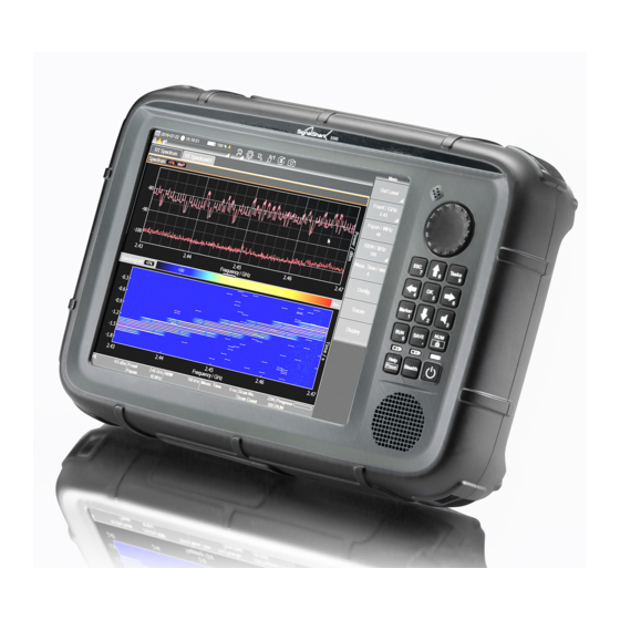
- Page 3 SignalShark - User Interface Manual SignalShark 3310 Handheld Device Overview Handheld Unit © Narda Safety Test Solutions GmbH www.narda-sts.com Slide 2...
- Page 4 › Hot-swappable for interruption-free long-term measurements › Batteries commercially available, Type: RRC2057, Li-ion, 48 Wh › Internal and external charging › Car-charger available › Operating time: approx. 3 hours © Narda Safety Test Solutions GmbH www.narda-sts.com Slide 3...
- Page 5 LEDs to indicate the operating status separately for batteries as well as for the operating status of the device. Built-in help function, Stealth mode, keyboard and touch lock © Narda Safety Test Solutions GmbH www.narda-sts.com Slide 4...
- Page 6 SignalShark 3310 Device Overview Built-in weather sealed loudspeaker gives clear, loud sound reproduction, even in noisy environments 10.4“ resistive touch screen › Intuitive operation, even when wearing gloves › Shielded for extreme EMC immunity © Narda Safety Test Solutions GmbH www.narda-sts.com Slide 5...
- Page 7 DC voltage for active antenna is supplied 4) Micro SD card slot (microSDXC) 5) PPS/trigger SMA(f) input 6) 1 GigE connector for remote control and I/Q streaming 7) DC input / charging jack © Narda Safety Test Solutions GmbH www.narda-sts.com Slide 6...
-
Page 8: Connector Panel
Connector Panel 8) 3 x RF SMA(f) input 9) RF N(f) input for connecting the antenna 10) 12-pin jack for connecting the antenna control cable 11) 10 MHz Ref SMA(f) input © Narda Safety Test Solutions GmbH www.narda-sts.com Slide 7... - Page 9 SignalShark - User Interface Manual SignalShark 3320 Device Overview Bottom View 1) USB 2.0 connection 2) Display Port Note: Display Port and USB connector can be used to connect an external touch screen. © Narda Safety Test Solutions GmbH www.narda-sts.com Slide 8...
-
Page 10: Battery Operation
› Charging times for a complete charging cycle are as follows: › When both batteries are charged in the device: approx. 4.2 hours (nom.) › When charged in external charger: approx. 3 hours (nom.) © Narda Safety Test Solutions GmbH www.narda-sts.com Slide 9... - Page 11 › LED lights up red: Device is in initialization phase or an error occurred › LED lights up green: Device is operational › LED flashes green: Device is in stealth mode › © Narda Safety Test Solutions GmbH www.narda-sts.com Slide 10...
- Page 12 In touch lock you can operate the device via a mouse emulation. The mouse pointer can be controlled by the arrow keys. A short press on the OK button will emulate a mouse left click. © Narda Safety Test Solutions GmbH www.narda-sts.com Slide 11...
- Page 13 › A long press on the Help/Preset button will load and apply the default task. Warning: All existing Tasks will be removed when applying the default setup! © Narda Safety Test Solutions GmbH www.narda-sts.com Slide 12...
- Page 14 › Hold: Display update is on hold, but measurement acquisition still runs in the background (trace data will be collected). Note: Spectrogram marker can only be used, if measurement is on hold or stopped. © Narda Safety Test Solutions GmbH www.narda-sts.com Slide 13...
- Page 15 Note: Single Run can be used to measure a defined number of measurement cycles or over a specified period of time (e.g. for Spectrum AVG trace, RMS channel power). © Narda Safety Test Solutions GmbH www.narda-sts.com Slide 14...
- Page 16 SignalShark 3310 Device Overview Special Hard Keys › Volume/Mute › A short press on the Volume/Mute button opens the volume settings menu. › A long press on the Volume/Mute button switches system sound on/off. © Narda Safety Test Solutions GmbH www.narda-sts.com Slide 15...
- Page 17 SignalShark - User Interface Manual SignalShark 3320 Remote Unit Device Overview Remote Unit © Narda Safety Test Solutions GmbH www.narda-sts.com Slide 16...
- Page 18 LED LINK lights up green: 1 Gbit The device starts automatically when connected to the › LED ACT lights green: Traffic power supply. The device can also be started via WakeOnLan (WOL). © Narda Safety Test Solutions GmbH www.narda-sts.com Slide 17...
-
Page 19: Front Panel
› QR codes including P/N, S/N, Mac address, etc. 6) Display port 7) USB 2.0 connection Note: Display Port and USB connector can be used to connect an external touch screen © Narda Safety Test Solutions GmbH www.narda-sts.com Slide 18... -
Page 20: Back Panel
SignalShark 3320 Device Overview Back Panel 1) 3 x RF SMA(f) input 2) RF N(f) input 3) 12-pin jack for connecting the antenna control cable 4) 10 MHz Ref SMA(f) input, 600 Ohm © Narda Safety Test Solutions GmbH www.narda-sts.com Slide 19... - Page 21 8) Micro SD card slot (microSDXC) 9) PPS / trigger SMA(f) input, 100 kOhm 10) 1 GigE connector › For remote control, I/Q streaming, and network connection, e.g. the Internet access for Win10 11) DC input © Narda Safety Test Solutions GmbH www.narda-sts.com Slide 20...
- Page 22 WARNING: This can lead to loss of data! › Device Operating Status LED › LED lights up red: Device is in initialization phase or an error occurred › LED lights up green: Device is operational © Narda Safety Test Solutions GmbH www.narda-sts.com Slide 21...
-
Page 23: Screen Layout
SignalShark - User Interface Manual Screen Layout Brief introduction to the most important GUI components © Narda Safety Test Solutions GmbH www.narda-sts.com Slide 22... - Page 24 SignalShark - User Interface Manual Screen Layout 1) System Information Area › Briefly displays the most important system information like › Date/Time › Battery status › GNSS status › Mute / Touch lock © Narda Safety Test Solutions GmbH www.narda-sts.com Slide 23...
- Page 25 SignalShark - User Interface Manual Basic Operation 1) System Information Area › A tap on the dropdown icon opens the system information menu © Narda Safety Test Solutions GmbH www.narda-sts.com Slide 24...
-
Page 26: System Information Menu
Please use the System Settings menu to change system settings. › You can leave the menu by › Pressing the Esc. hard key or › A short tap on the Button Bar Header © Narda Safety Test Solutions GmbH www.narda-sts.com Slide 25... - Page 27 Save Measurement Tap to save the current measurement. Screenshot Tap to store a screenshot from the current display. Undo/Redo Tap the dropdown icon to open the action history. © Narda Safety Test Solutions GmbH www.narda-sts.com Slide 26...
- Page 28 Tap to open the Marker menu. Scripting (if installed) Tap to start NardaScriptLauncher Additional Functions Menu Tap to open a dropdown window with additional functions like: Volume/Mute, Configure Views, Preset or Help © Narda Safety Test Solutions GmbH www.narda-sts.com Slide 27...
- Page 29 On many sites, several kinds of signals in different frequency bands have to be analyzed. That’s why SignalShark replaces the conventional concept of measurement modes by the Tasks and Views concept. © Narda Safety Test Solutions GmbH www.narda-sts.com Slide 28...
- Page 30 Tasks encapsulate all measurement parameters and the underlying measurement acquisition. › Within a task, all measurements are performed at the same time. Note: Only one task can be active and doing measurement at a time. © Narda Safety Test Solutions GmbH www.narda-sts.com Slide 29...
- Page 31 SignalShark - User Interface Manual Screen Layout 3) Task Bar › Browser like tap bar, that enables quick switching between measurement settings and different task types. © Narda Safety Test Solutions GmbH www.narda-sts.com Slide 30...
-
Page 32: Task Types
3.125 µs POI. Auto DF Mode › The Auto Direction Finding task type supports control of the automatic DF antennas and handles the calculation of bearings out of the DF data. © Narda Safety Test Solutions GmbH www.narda-sts.com Slide 31... - Page 33 The type, arrangement and size of a View can be adapted by the user. Note: It is possible to save the current configuration and arrangement of Tasks and Views into setup files. © Narda Safety Test Solutions GmbH www.narda-sts.com Slide 32...
-
Page 34: Screen Overview
5) Button Bar › Provides access to the measurement and display settings of the currently selected View. Note: The content and layout of the “Button Bar” depends on the currently selected View. © Narda Safety Test Solutions GmbH www.narda-sts.com Slide 33... - Page 35 6) Measurement Information Bar › Displays the most relevant settings of the currently selected View. Note: The content and layout of the “Measurement Information Bar” depends on the currently selected View. © Narda Safety Test Solutions GmbH www.narda-sts.com Slide 34...
-
Page 36: Basic Operation
SignalShark - User Interface Manual Basic Operation The basic operating steps © Narda Safety Test Solutions GmbH www.narda-sts.com Slide 35... -
Page 37: Touch Screen Control
SignalShark - User Interface Manual Basic Operation Touch Screen Control SignalShark uses two basic touch gestures › Single Tap › Swipe © Narda Safety Test Solutions GmbH www.narda-sts.com Slide 36... - Page 38 To add a new measurement task: › Tap on the Edit Task icon in the Task Bar › Press the “Task” hard key © Narda Safety Test Solutions GmbH www.narda-sts.com Slide 37...
- Page 39 SignalShark - User Interface Manual Basic Operation Add new Task Step 2 › Tap on the “Add Task” button in the “Tasks” Button Bar. © Narda Safety Test Solutions GmbH www.narda-sts.com Slide 38...
- Page 40 It is possible to save user defined task configurations as setups. A tap on the Predefined Setups item will open the setup menu from where a predefined setup can be loaded. © Narda Safety Test Solutions GmbH www.narda-sts.com Slide 39...
- Page 41 SignalShark - User Interface Manual Basic Operation Maximizing a View A View can be maximized by a single tab on the maximize Icon › › Tapping again on the button will resize the View. © Narda Safety Test Solutions GmbH www.narda-sts.com Slide 40...
- Page 42 Change View Arrangement To change the arrangement of the Views: › Tap on the Menu Tool button › Tap on the Configure Task Views button. The “Configure Task Views” submenu opens © Narda Safety Test Solutions GmbH www.narda-sts.com Slide 41...
- Page 43 To add a View to the Task: › Tap on the desired View Type in the “Configure Task Views” Button Bar › Tap on the desired position of the new View. © Narda Safety Test Solutions GmbH www.narda-sts.com Slide 42...
- Page 44 SignalShark - User Interface Manual Basic Operation Change View Position Step 1 To change the position of a View: › Tap on the Move Button © Narda Safety Test Solutions GmbH www.narda-sts.com Slide 43...
- Page 45 SignalShark - User Interface Manual Basic Operation Change View Position Step 2 › Tap on the desired position. © Narda Safety Test Solutions GmbH www.narda-sts.com Slide 44...
- Page 46 SignalShark - User Interface Manual Basic Operation Delete View To delete a View from the Task: › Tap on the Delete Button © Narda Safety Test Solutions GmbH www.narda-sts.com Slide 45...
-
Page 47: Back To The Main Menu
To get back to the main menu: › Tap on the header button of the “Configure Task Views” Button Bar or › Press the “Esc/Back” hard key Note: This is the default way to leave a submenu. © Narda Safety Test Solutions GmbH www.narda-sts.com Slide 46... - Page 48 SignalShark - User Interface Manual Basic Operation Show the Amplitude Menu To display the Amplitude Menu: › Tap on the Parameter Split Button › Ref. Lev. | Atten. © Narda Safety Test Solutions GmbH www.narda-sts.com Slide 47...
-
Page 49: Amplitude Menu
Basic Operation Amplitude Menu The Amplitude Menu contains manly settings to adapt the measurement to the current signal level like: › Reference Level › Attenuator It contains also the RF input selection © Narda Safety Test Solutions GmbH www.narda-sts.com Slide 48... - Page 50 SignalShark - User Interface Manual Basic Operation Show the Frequency Menu To display the Frequency Menu: › Tap on the Parameter Button › Fcent/Fstart or › Fspan/Fstop © Narda Safety Test Solutions GmbH www.narda-sts.com Slide 49...
-
Page 51: Frequency Menu
SignalShark - User Interface Manual Basic Operation Frequency Menu The Frequency Menu displays all frequency related parameters: It contains also the selection of the Rotary Knob input mode. © Narda Safety Test Solutions GmbH www.narda-sts.com Slide 50... - Page 52 SignalShark - User Interface Manual Basic Operation Set Frequency Span by Touch The frequency span can be set by selecting/drawing a horizontal range inside the graph from the left to the right. © Narda Safety Test Solutions GmbH www.narda-sts.com Slide 51...
- Page 53 SignalShark - User Interface Manual Basic Operation Set Frequency Span by Touch Dragging from right to the left within the graph area will double the span. © Narda Safety Test Solutions GmbH www.narda-sts.com Slide 52...
- Page 54 SignalShark - User Interface Manual Basic Operation Y-Axis Auto Range The display range of the y-axis can be automatically adapted by a tap on the Auto Range button. © Narda Safety Test Solutions GmbH www.narda-sts.com Slide 53...
- Page 55 SignalShark - User Interface Manual Basic Operation Set Center Frequency by Touch The center frequency can be set by dragging the frequency axis to the left or to the right. © Narda Safety Test Solutions GmbH www.narda-sts.com Slide 54...
-
Page 56: Marker Menu
SignalShark - User Interface Manual Basic Operation Marker Menu To open the Marker Menu › Tap on the Marker Menu Tool Button or › Press the hard key “Marker” © Narda Safety Test Solutions GmbH www.narda-sts.com Slide 55... -
Page 57: Add Marker
SignalShark - User Interface Manual Basic Operation Add Marker Select one to eight markers in the marker menu to add a marker. © Narda Safety Test Solutions GmbH www.narda-sts.com Slide 56... - Page 58 Change Marker Position by Touch To change the marker position 1) Tap on the marker label to select it 2) Then drag the marker by it’s label to the desired position. © Narda Safety Test Solutions GmbH www.narda-sts.com Slide 57...
- Page 59 SignalShark - User Interface Manual Basic Operation Change Marker Settings Step 1 To change marker settings › Tap on the Marker Config. button in the “Marker” Button Bar © Narda Safety Test Solutions GmbH www.narda-sts.com Slide 58...
- Page 60 Select a category tap in the “Marker Config” menu. › Tap in the table cell you want to change. › I.e. a tap in the cell “Type” toggles the marker type from normal marker to delta marker. © Narda Safety Test Solutions GmbH www.narda-sts.com Slide 59...
- Page 61 Basic Operation Change Device Settings Step 1 To change a device setting like the display brightness: › Tap on the Device Settings Tool Button The Device Settings menu will appear. © Narda Safety Test Solutions GmbH www.narda-sts.com Slide 60...
- Page 62 A Parameter Edit Window will appear where the new setting can be entered. Note: Editable table cells have a different color than headlines or table cells containing a description. © Narda Safety Test Solutions GmbH www.narda-sts.com Slide 61...
- Page 63 The Working Directory defines the place (drive and folder) where data is saved to. To change the current Working Directory: › Tap on the Data Logger Tool Button The Data Logger menu will appear. © Narda Safety Test Solutions GmbH www.narda-sts.com Slide 62...
- Page 64 Select Working Directory Step 1 › Select the drive/folder that should be set as Working Directory › Tap on “Set as Working Directory” Note: The actual Working Directory is marked with a green dot. © Narda Safety Test Solutions GmbH www.narda-sts.com Slide 63...
- Page 65 SignalShark - User Interface Manual Localization in three Steps with AutoDF Using AutoDF Task © Narda Safety Test Solutions GmbH www.narda-sts.com Slide 64...
- Page 66 SignalShark - User Interface Manual Localization in three Steps with AutoDF 1) Load a Predefined Setup › Open the “Add Task” menu › Select the “Predefined Setups” item © Narda Safety Test Solutions GmbH www.narda-sts.com Slide 65...
- Page 67 Map. Mode is “Disc. Localization” (Tap on “Save” to store a bearing) Vehicle: › The antenna is mounted on a vehicle › Map. Mode is “Cont. Localization” (Bearings are recorded into a file) © Narda Safety Test Solutions GmbH www.narda-sts.com Slide 66...
-
Page 68: Adjust Settings
Adjust the bearing settings according to your signal › Ftune › CBW › Attenuation › Adjust the bearing configuration settings according to your signal conditions › DF Squelch › Min. DF Quality © Narda Safety Test Solutions GmbH www.narda-sts.com Slide 67... - Page 69 Localization in three Steps with AutoDF 3) Start Localization › Select the Map View (optional) › Tap on “Start Localization” Note: The default “Localization Area” is 50 km x 50 km around your current GNSS position. © Narda Safety Test Solutions GmbH www.narda-sts.com Slide 68...
- Page 70 Then look at the heat map and turn left or right depending on the result and drive again some kilometers Note: An ideal localization is the result of ideal bearings intersecting at right angles as in an “L” pattern. © Narda Safety Test Solutions GmbH www.narda-sts.com Slide 69...