Advertisement
http://www.narda-sts.it
User's Manual
ARTIFICIAL MAINS NETWORKS
SERIAL NUMBER OF THE INSTRUMENT
You can find the Serial Number on the rear panel of the instrument.
Serial Number is in the form: 0000X00000.
The first four digits and the letter are the Serial Number prefix, the last five digits are
the Serial Number suffix. The prefix is the same for identical instruments, it changes
only when a configuration change is made to the instrument.
The suffix is different for each instrument.
Document L3EN-70206 - Copyright © NARDA 2007
Sales & Support:
NARDA
Via Leonardo da Vinci, 21/23
Safety
20090 Segrate (MI) -
Test
Tel.: +39 02 2699871
Solutions
Fax: +39 02 26998700
S.r.l. Socio Unico
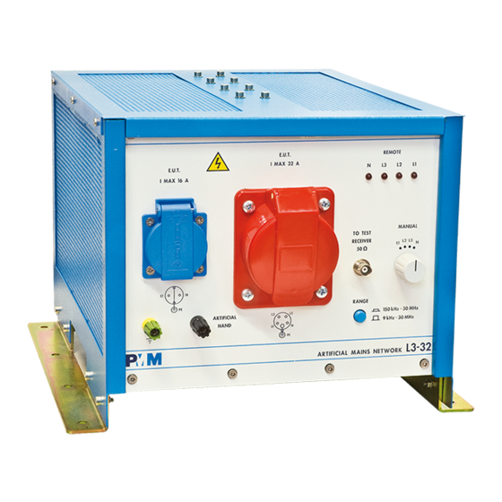
PMM L3-32
PMM L3-64
PMM L3-100
PMM L3-500
Manufacturing Plant:
Via Benessea, 29/B
17035 Cisano sul Neva (SV)
ITALY
Tel.: +39 0182 58641
Fax: +39 0182 586400
Advertisement

Related Manuals for NARDA PMM L3-64


Summary of Contents for NARDA PMM L3-64
- Page 1 The first four digits and the letter are the Serial Number prefix, the last five digits are the Serial Number suffix. The prefix is the same for identical instruments, it changes only when a configuration change is made to the instrument. The suffix is different for each instrument. Document L3EN-70206 - Copyright © NARDA 2007...
- Page 2 Union (2002/96/EC) and belongs to Category 9 (Monitoring and Control Instruments). You can return the instrument to us free of charge for proper environment friendly disposal. You can obtain further information from your local Narda Sales Partner or by visiting our website at www.narda-sts.it .
-
Page 3: Table Of Contents
Contents Page Safety considerations and instructions..….…………… EC Conformity Certicate PMM L3-32....…... EC Conformity Certicate PMM L3-64....…..VIII EC Conformity Certicate PMM L3-100......EC Conformity Certicate PMM L3-500......1 General Information Page 1.1 Documentation........……..... 1.2 Introduction to PMM Artificial Mains Network…………... - Page 4 PMM L3-32 Network schematic diagram………………….. PMM L3-32 Network schematic diagram………………….. PMM L3-64 Front Panel……………………………………… PMM L3-64 Rear Panel……………………………………… PMM L3-64 Network schematic diagram………………..…. PMM L3-64 Network schematic diagram………………..…. PMM L3-100 Front Panel…………………………………..… PMM L3-100 Rear Panel………………………...…………... PMM L3-100 Network schematic diagram………………..
- Page 5 • To prevent the possible danger of electrocution, do not remove any covers, panels or guards installed on the device, and refer only to NARDA Service Centers if maintenance should be necessary; • To maintain adequate protection from fire hazards, replace fuses only with others of the same type and rating;...
- Page 6 E C C o n f o r m i t y C e r t i f i c a t e (in accordance with the Directives: EMC 89/336/EEC and Low Voltage 73/23/EEC) This is to certify that the product: PMM L3-32 Artificial Mains Network Produced by: NARDA S.r.l. Safety Test Solution Via Benessea 29/B 17035 Cisano sul Neva (SV) –...
- Page 7 E C C o n f o r m i t y C e r t i f i c a t e (in accordance with the Directives: EMC 89/336/EEC and Low Voltage 73/23/EEC) This is to certify that the product: L3-64 Artificial Mains Network Produced by: NARDA S.r.l. Safety Test Solution Via Benessea 29/B 17035 Cisano sul Neva (SV) –...
- Page 8 E C C o n f o r m i t y C e r t i f i c a t e (in accordance with the Directives: EMC 89/336/EEC and Low Voltage 73/23/EEC) This is to certify that the product: PMM L3-100 Artificial Mains Network Produced by: NARDA S.r.l. Safety Test Solution Via Benessea 29/B 17035 Cisano sul Neva (SV) –...
- Page 9 E C C o n f o r m i t y C e r t i f i c a t e (in accordance with the Directives: EMC 89/336/EEC and Low Voltage 73/23/EEC) This is to certify that the product: PMM L3-500 Artificial Mains Network Produced by: NARDA S.r.l. Safety Test Solution Via Benessea 29/B 17035 Cisano sul Neva (SV) –...
- Page 10 This page has been left blank intentionally EC Conformity...
-
Page 11: Documentation
Enclosed with this manual are a service questionnaire to send back to 1.1 Documentation NARDA in case of equipment service is needed, and an accessories check list to verify all accessories enclosed in the packaging. The objective of EMI Conducted tests is to define the amplitude of current I 1.2 Introduction to PMM... -
Page 12: Injection" Test
1-3 PMM Artificial Mains As described above, a LISN is primarily a probe to take out RF signals. Some particular EMC recommendations might require that Device Under Networks for Test shall be proven to conducted EMC immunity in the range 10 kHz – 30 “CURRENT MHz, by injecting on the supply lines certain RF interference and checking INJECTION”... -
Page 13: Shipping Components
-25° to + 75° C < 95% relative • Humidity If the instrument should be returned to NARDA for service, please complete 1-6 Return for service the service questionnaire enclosed with the Operating Manual and attach it to the instrument. - Page 14 This page has been left blank intentionally General Information...
- Page 15 32 A IEC connector and 16A Schuko Rated temperature: 0° to + 40° C -25° to + 75° C Storage temperature: 342 x 254 x 370 Overall dimension mm (W x H x D): 16.5 kg Weight: Document L3EN-70206 - © NARDA 2007 PMM L3-32...
-
Page 16: Front And Rear Panels
2-2 Front and Rear In Fig. 2-1 and Fig. 2-2 you can see front and rear connecting points and terminals of PMM L3-32 Network. Panels Fig. 2-1 Front Panel Fig. 2-2 Rear Panel Legend: 5- Mains LISN supply. 1- Ground contact 6- Mains supply to DUT 16A Schuko 2- Mains supply to DUT 32A 7- Remote receiver control connector... -
Page 17: Network Schematic Diagram
2-3 Network schematic diagram Fig. 2-3 Network schematic diagram PMM L3-32... - Page 18 Fig. 2-4 Network schematic diagram PMM L3-32...
- Page 19 Fig. 2-5 Network schematic diagram PMM L3-32...
- Page 20 This page has been left blank intentionally PMM L3-32...
- Page 21 3 – PMM L3-64 Table 3-1 lists the PMM L3-64 Network performance specifications. The following conditions apply to all specifications: • The ambient temperature must be 0° to 40°. 3-1 Main specifications TABLE 3-1 Main specifications PMM L3-64 Electrical characteristics...
- Page 22 In Fig. 3-1 and Fig. 3-2 you can see front and rear connecting points and 3-2 Front and Rear terminals of PMM L3-64 Network. Panels Fig. 3-1 Front Panel Fig. 3-2 Rear Panel Legend: 4- RF output to EMI Signal Analyzer (50 ohm,...
- Page 23 3-3 Network schematic diagram Fig. 3-3 Network schematic diagram PMM L3-64...
- Page 24 Fig. 3-4 Network schematic diagram PMM L3-64...
- Page 25 0° to + 40° C Rated temperature: - 25° to + 75° C Storage temperature: 400 x 405 x 450 Overall dimension mm (W x H x D): 70 kg Weight: 100 kg Gross weight Document L3EN-70206 - © NARDA 2007 PMM L3-100...
- Page 26 In Fig. 4-1 and Fig. 4-2 you can see front and rear connecting points and 4-2 Front and Rear terminals of PMM L3-100 Network. Panels Fig. 4-1 Front Panel Fig. 4-2 Rear Panel Legend: 4- RF output to EMI Signal Analyzer (50 ohm, 1- Ground contact BNC female connector) 2- Mains supply to DUT...
- Page 27 4-3 Network schematic diagram Fig. 4-2 Network schematic diagram PMM L3-100...
- Page 28 Fig. 4-3 Network schematic diagram PMM L3-100...
- Page 29 500 A bolts Rated temperature: 0° to + 40° C - 25° to + 75° C Storage temperature: Overall dimension mm (W x H x D): 555 x 1240 x 400 210 kg Weight: Document L3EN-70206 - © NARDA 2007 PMM L3-500...
- Page 30 In Fig. 5-1 and Fig. 5-2 you can see front and rear connecting points and 5-2 Front and Rear terminals of PMM L3-500 Network. Panels Fig. 5-1 Front Panel Legend: 4- Mains LISN supply, to EUT 1- “power on” led 5- Protective earth 2- “voltage present”...
- Page 31 Fig. 5-2 Rear Panel Legend: 4- Fan supply 1- Pilot circuit output 5- Fan supply switch 2- Mains LISN supply 3- Protective earth PMM L3-500...
- Page 32 This page has been left blank intentionally PMM L3-500...
-
Page 33: Initial Inspection 6.3 Packing Unpacking
Verify the accessories availability in the shipping container referring to the accessories check list enclosed with the Operating Manual. Notify any damage to the carrier as well as the NARDA Representative. To remove the LISN, open the wooden box and unscrew the four screws that hold the LISN at the bottom side of the palette. -
Page 34: Preparation For Use...................................................... 6-2
From the mains lines conductor to the case of the unit there is a high 6-4 Preparation for use leakage current. The mains lines conductor is connected to ground via high value capacitors due to the measurement system to be applied. Over current protection is not provided in the LISN. - Page 35 6-6 Installation Check list Before operation ensure the following steps are taken: • Check the line voltage to ensure the compatibility with the equipment requirements. • Ensure that the to be provided fuse or breaker current rating is appropriate for the equipment setup. •...
- Page 36 This page has been left blank intentionally Installation...
- Page 37 The PMM LISN continuous operation at higher current limit shall not exceed one hour, a rest period of at least a half hour shall be observed to allow the equipment to cool down. Document L3EN-70206 - © NARDA 2007 Operating PMM Networks...
-
Page 38: Typical Test Set-Up
All dimensions are given in centimeters. Internal hardware checks and repairs shall be performed only by NARDA authorized assistance and service centers. The manufacturer, the worldwide distributors and the national distributor agents shall not be responsible and kept liable for... - Page 39 Spectrum Analyzer input). 3. Attenuation between generated signal level and measured level on output shall be less than 0.5dB at 1 MHz. If higher than 0.5 dB, please refer to qualified NARDA Service Center for maintenance of the unit. Operating PMM Networks...
- Page 40 7.4 Remote receiver control connector Legend: • 1 = (A) • 2 = (B) • 3 = (+12V) • 4 = (GND) Legend: • • Operating PMM Networks...
- Page 41 Mod. 18-1 Caro cliente grazie per aver acquistato un prodotto NARDA! Sei in possesso di uno strumento che per molti anni ti garantirà un’alta qualità di servizio. NARDA riconosce l'importanza del Cliente come ragione di esistenza; ciascun commento e suggerimento, sottoposto all'attenzione della nostra organizzazione, è...
- Page 42 Suggerimenti / Commenti / Note: Suggestions / Comments / Note:...