
Related Manuals for NARDA ELT-400


Summary of Contents for NARDA ELT-400
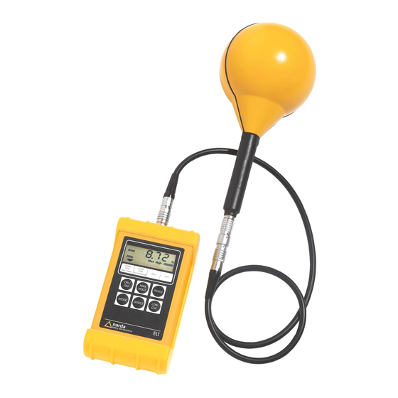
- Page 1 ® Advanced Test Equipment Rentals www.atecorp.com 800-404-ATEC (2832) ELT-400 Exposure Level Tester Operating Manual...
- Page 3 ELT-400 Exposure Level Tester BN 2304/xx, Series A ... Operating Manual...
- Page 4 If you have any questions about this product, please contact your local Sales Partner. Narda Safety Test Solutions GmbH Sandwiesenstr. 7, 72793 Pfullingen © 2004 Order no.: 2300/98.11 Edition : 03/04.07, A ... Previous Edition: 02/03.08, A ... Subject to change...
-
Page 5: Table Of Contents
Contents Introduction ........1-1 About this instrument..... . 1-1 1.1.1 Application. - Page 6 Measuring....... 5-6 5.3.1 Switching the ELT-400 on and off ... . . 5-6 5.3.2 Selecting the operating mode (MODE).
- Page 7 Remote control ....... . . 7-1 Setting up the data link ....7-1 7.1.1 Data cable .
- Page 8 Notes:...
-
Page 9: Introduction
In practice, simple equipment must be used to determine the fields that occur and to check that the limit values are not exceeded. The ELT-400 is a completely new type of tester for workplace and public area exposure to magnetic radiation. It was developed specially for the above areas, for use by health and safety representatives in industry, insurers, and service providers. - Page 10 EN 50366 and prEN 50392 is implemented precisely in this instrument. Instrument description The ELT-400 is extremely easy to operate using just 6 buttons and can be used practically anywhere. Exposure STD mode...
-
Page 11: About This Manual
ELT-400 1 Introduction 1.1.2 About this manual Typographic conventions Some special symbols are used in certain paragraphs to make it easier to read and understand this manual. This symbol indicates a cross-reference to another chapter, section or document. Note: This indicates important additional information or notes concerning special features or situations ✓... - Page 12 1 Introduction ELT-400 Notes:...
-
Page 13: Safety Instructions
Safety instructions Before connecting up This instrument was shipped in perfect condition. Please follow the instructions below to ensure that this condition is maintained and that operation remains safe. Correct usage The instrument must only be used under the conditions and for the purpose for which it has been designed. - Page 14 2 Safety instructions ELT-400 Electric shock Very high voltages can occur inside the instrument. ⇒ Make sure that the instrument or the probe does not touch any part carrying a voltage. Danger ⇒ Do not open the instrument. ⇒ Do not use an instrument which is opened or which is visibly damaged.
-
Page 15: Ac Adapter / Charger Unit
ELT-400 2 Safety instructions AC adapter / charger unit Electric shock Parts carrying dangerous voltages that may cause injury may be exposed if the AC adapter / charger unit is damaged. Danger ⇒ Do not use an AC adapter / charger unit that has been damaged. - Page 16 2 Safety instructions ELT-400 Notes:...
-
Page 17: Preparation For Use
Preparation for use Unpacking 3.1.1 Packaging The packaging is designed to be re-used as long as it has not been damaged during previous transport. Please therefore keep the original packaging and use it whenever you want to transport the instrument in future. -
Page 18: Power Supply
• Avoid incorrect polarity. • Do not short-circuit the battery contacts. • If possible, leave the ELT-400 connected to the AC adapter / charger unit to ensure that it is always ready for use. • Do not leave discharged batteries in the instrument for a long period of time. -
Page 19: Charging The Rechargeable Batteries
The charge cycle is still indicated if the AC adapter / charger unit is disconnected from the AC line after charging has started but remains connected to the ELT-400. If charging seems to be taking an unusually long time, check that the connection to the AC line... -
Page 20: Preparing For Field Measurements
Connecting / disconnecting the B field probe The multi-pin connector socket for the B field probe is located at the top of the ELT-400. The field probe is secured by means of a sliding locking sleeve. Sliding locking sleeve Fig. 3-1... - Page 21 ELT-400 3 Preparation for use Disconnecting the field probe ⇒ Hold the field probe by the locking sleeve and pull it off the basic instrument.
- Page 22 3 Preparation for use ELT-400 Notes:...
-
Page 23: Control And Display Elements
Control and display elements The instrument diagram in the Annex shows the positions of all control and display elements. Keypad Function ON/OFF On / off key • Starts the instrument with its default settings. • Switches the display backlight on or off (press briefly) •... - Page 24 4 Control and display elements ELT-400 Function MODE Operating mode selection key • Switches between “Exposure STD” and “Field strength” modes. • Switches between standardized evaluation schemes and measurement ranges. • All evaluation schemes and measurement ranges implemented in the instrument are shown beneath the display.
-
Page 25: Lcd Display
ELT-400 4 Control and display elements LCD display 4.2.1 LCD display elements Fig. 4-1 LCD elements (example) Function Measured value including units The units depend on the selected measurement mode • % • µT, mT Table 4-2 LCD display elements... - Page 26 • Inner segments displayed to indicate the charge level. • Outer frame flashes. Batteries discharged • All inner segments off. • To avoid deep discharge, the ELT-400 switches off automatically after about 15 minutes. • The battery symbol is no longer Batteries fully discharged or not displayed at all.
-
Page 27: Display Backlight
ELT-400 4 Control and display elements Function Display of selected lower frequency range limit: • 1 Hz • 10 Hz • 30 Hz Selected operating mode indicated by arrow symbol. Display of selected detection mode: • RMS = root mean square value. -
Page 28: External Connectors
4 Control and display elements ELT-400 External connectors There are three connector sockets for external equipment on the left side of the instrument. Socket Function Serial data interface Computer (PC) connection • 19200 baud • 8n1 RS-232 • Handshake XON/XOFF •... -
Page 29: Operation And Use
The user simply selects the desired standard. The required frequency response for the limit values is emulated by means of internal filters. Advantages of the ELT-400: • Instant display of current situation and safety margin without needing to refer to the standards. -
Page 30: Exposure Std (Shaped Time Domain)
5 Operation and use ELT-400 5.1.1 Exposure STD (Shaped Time Domain) Broadband measurement with simultaneous real-time exposure assessment Fig. 5-1 Measurement display in “Exposure STD” mode Measurement goal: Rapid, reliable assessment of field exposure with reference limits from a selected standard. -
Page 31: Field Strength
ELT-400 5 Operation and use 5.1.2 Field strength Broadband real time measurement of magnetic flux density Fig. 5-2 Measurement display in “Field strength” mode Measurement goal: Measurement of overall field strength. Measured quantity: RMS or peak flux density value. Display: Numerical display of measurement result in units of mT or µT. -
Page 32: Example Applications
5 Operation and use ELT-400 Example applications To take advantage of the full performance of the ELT-400, it is important to optimize the instrument settings to match the expected characteristics of the field being investigated. The table below provides assistance for this important task. - Page 33 ELT-400 5 Operation and use Application Characteristic feature Recommended instrument setting • MODE: Electronic article Complex pulse shape, surveillance 20 Hz to 10 kHz Exposure STD (gen. pub.) • RANGE: High (electromagnetic) • LOW CUT: 10 Hz • MODE: Electronic article...
-
Page 34: Measuring
5 Operation and use ELT-400 Measuring 5.3.1 Switching the ELT-400 on and off Switching the ELT-400 on ✓ You have made sure of the power supply ⇒ Press the ON/OFF key briefly. The basic instrument switches on. The function test runs. - Page 35 – the measurement display appears. – You can now start making measurements. Fig. 5-4 Measurement display Switching off the ELT-400 ⇒ Press and hold down the ON/OFF key for about 3 seconds. The basic instrument switches off. Possible faults No display after switch on The rechargeable batteries or alkaline batteries are completely discharged.
-
Page 36: Selecting The Operating Mode (Mode)
5 Operation and use ELT-400 The display shows the error message “noPr”. The probe is not connected or has not been detected by the instrument. ⇒ Remove the probe and reconnect it. Connecting / disconnecting the B field probe: see page 3-4 The display shows the error message “unPr”. -
Page 37: Selecting The Detection Mode (Detect)
ELT-400 5 Operation and use 5.3.3 Selecting the detection mode (DETECT) Three modes of detection are available depending on the selected operating mode: Detection mode / Detector: see page C-2 Detection mode Field Exposure strength STD mode mode STND (Standard) The detection mode specified in the appropriate standard is set automatically. -
Page 38: Selecting The Lower Frequency Range Limit (Low Cut)
5 Operation and use ELT-400 5.3.4 Selecting the lower frequency range limit (LOW CUT) The default measurement range setting is limited to 30 Hz to 400 kHz. The lower frequency range limit can be extended down to 1 Hz or 10 Hz. -
Page 39: Activating The Max Hold Display Function
ELT-400 5 Operation and use Note: The measurement display will fluctuate whenever the setting is changed. This fluctuation depends on the selected lower frequency range limit and may continue for several seconds, particularly if 1 Hz or 10 Hz is selected. Wait until the display has settled before starting measurements. -
Page 40: Interpreting The Measurement Results
5 Operation and use ELT-400 5.3.7 Interpreting the measurement results Fig. 5-5 Measurement display showing measurement result Explanation Numerical value of measurement result The following applies to “Exposure STD” mode: The percentage displayed refers to the limit value specified in the selected safety standard. - Page 41 The selected measurement range is unsuitable for the measurement task. 1. Select HIGH range. 2. If the overload display is still shown, increase the distance of the ELT-400 from the field source. Selecting the measurement range (RANGE): see page 5-10 –...
-
Page 42: Active Probe (Using The Three-Channel Analog Output)
An oscilloscope or FFT analyzer can be connected to the analog signal output (Scope) of the ELT-400 for this purpose. External connectors: see page 4-6 The analog signal output provides the signal voltages for all three spatial axes with their correct phases and covers the entire bandwidth of the instrument. - Page 43 ELT-400 5 Operation and use Example Sinusoidal signal in range 10–500 Hz, measured in Exposure STD mode • Analog output voltages on channels X, Y and Z are phase-shifted relative to the measured field strength by approx. 90° (due to the differentiating transfer function in Exposure STD mode).
- Page 44 5 Operation and use ELT-400 Notes: 5-16...
-
Page 45: Maintenance And Repairs
6.1.1 Replacing the rechargeable batteries and alkaline batteries ✓ The ELT-400 is switched off ✓ The ELT-400 is disconnected from the AC adapter / charger unit Changing the rechargeable or alkaline batteries 1. Remove the probe. 2. Starting from the lower side of the instrument, slide off the rubber cover. -
Page 46: Disposal Of Alkaline And Rechargeable Batteries
Return them to the appropriate recycling center. Cleaning • Do not use solvents to clean the casing or probes of the ELT-400 or the AC adapter / charger unit. Use lukewarm water to which a little liquid detergent has been added. -
Page 47: Remote Control
Remote control Setting up the data link You will need a suitable cable for making the link between the ELT-400 and the measurement computer. It is available as an accessory (BN 2260/90.51). 7.1.1 Data cable DB9 plug: Fig. 7-1 DB9 plug connections Jack plug: Fig. -
Page 48: Interface Parameters
7 Remote control ELT-400 Connecting the instrument to the measurement computer 1. Plug the jack plug into the “RS-232” socket on the ELT-400. 2. Plug the DB9 plug into the serial interface connector (COM) of the measurement computer. 7.1.2 Interface parameters ✓... -
Page 49: Fundamentals Of Remote Control
Annex A: Default values 7.2.1 Overview of remote control commands The ELT-400 runs through a test phase when you switch it on. This tests important settings and instrument configurations. The following remote control commands can be used to query or change the... - Page 50 7 Remote control ELT-400 The following remote control commands can additionally be used in the measurement phase: Remote control command CALC:BAT[?]<SP><param>[CR]<LF> see page 7-17 CALC:OVLD[?]<SP><param>[CR]<LF> see page 7-18 GET:MODE_INFO[?]<SP><STD><name>[CR]<LF> see page 7-8 MEAS[?][CR]<LF> see page 7-14 SEN:TYPE?[CR]<LF> see page 7-7 SET:DETECTOR[?]<SP><param>[CR]<LF>...
-
Page 51: Remote Control Command Format
ELT-400 7 Remote control 7.2.2 Remote control command format The following conventions are used to describe the remote control commands: Character Meaning Instrument parameter / measurement value query param Instrument status transfer parameter Optional information is given in square [brackets] <... -
Page 52: Response Value Formats
7 Remote control ELT-400 7.2.3 Response value formats Different formats are used for the values returned as responses by the ELT-400. Response strings are terminated with a “Carriage Return” and a “Line Feed”. It is a good idea to filter out and delete unnecessary characters before subjecting the received data to further processing. -
Page 53: Remote Control Commands
ELT-400 7 Remote control Remote control commands All the remote control commands used for the ELT-400 are described in this section. The commands are sorted according to their meanings. Field probe SEN:TYPE?[CR]<LF> Response: <param><CR><LF> Meaning: Returns the type of field probe connected. - Page 54 7 Remote control ELT-400 Measured quantity, evaluation mode GET:MODE_INFO?[CR]<LF> Response: <param>, <text><CR><LF> Meaning: Returns the operating mode that is selected. param Explanation “Field strength” mode “Exposure STD” mode Table 7-4 Operating mode characterization text Explanation Additional information: • End value (RMS value) if param = 0 •...
- Page 55 ELT-400 7 Remote control SET:DETECTOR<SP><param>[CR]<LF> SET:DETECTOR?[CR]<LF> Response: <param><CR><LF> Meaning: Selects the detection mode. param Explanation The RMS value measured using the selected operating mode will be output. PEAK The peak value measured using the selected operating mode will be output.
- Page 56 7 Remote control ELT-400 SET:LOW_CUT<SP><param>[CR]<LF> SET:LOW_CUT?[CR]<LF> Response: <param><CR><LF> Meaning: Sets the lower frequency range limit. param Explanation Defines 1 Hz as the lower frequency range limit. Defines 10 Hz as the lower frequency range limit. Defines 30 Hz as the lower frequency range limit.
- Page 57 ELT-400 7 Remote control SET:MAX_HOLD<SP><param>[CR]<LF> SET:MAX_HOLD?[CR]<LF> Response: <param><CR><LF> Meaning: Activates / deactivates the MAX HOLD display function. param Explanation Activate MAX HOLD display function • The highest value measured since the function was activated is output instead of the current measurement value.
- Page 58 7 Remote control ELT-400 SET:MODE<SP><param>[CR]<LF> SET:MODE?[CR]<LF> Response: <param><CR><LF> Meaning: Selects the operating MODE. The operating modes are numbered consecutively (1 to 4). The mode assigned to each number depends on the instrument version. param Explanation Displays the first operating mode counting from the left hand side of the display.
- Page 59 ELT-400 7 Remote control SET:RANGE<SP><param>[CR]<LF> SET:RANGE?[CR]<LF> Response: <param><CR><LF> Meaning: Sets the measurement range for the selected operating mode. param Explanation Measurement range particularly suitable for low field strengths • High measurement sensitivity. • Reduced overload capacity. HIGH Measurement range suitable for higher field strengths •...
- Page 60 7 Remote control ELT-400 MEAS Meaning: Transfers the measured values and, where appropriate, the status information. Different modes for transferring individual values and for transferring values continuously are provided. Remote control Explanation command MEAS?[CR]<LF> Transfers the latest measured value / status on request.
- Page 61 ELT-400 7 Remote control Response values: <d.dddesdd><, unit> [, ovld] [, bat] <CR><LF> Example: 1.234e-07, T, N, O Response Explanation unit Units of measured value; depends on the operating mode selected by SET:MODE • T = Tesla (in “Field strength” mode only) •...
- Page 62 7 Remote control ELT-400 SYST:KLOC<SP><param>[CR]<LF> SYST:KLOC?[CR]<LF> Response: <param><CR><LF> Meaning: Locks / unlocks the keypad of the basic instrument. param Explanation Locks the basic instrument keypad. The instrument does not respond if any of the operating keys are pressed in this status.
- Page 63 ELT-400 7 Remote control Instrument status query CALC:BAT<SP><param>[CR]<LF> CALC:BAT?[CR]<LF> Response: <param><CR><LF> Meaning: Activates / deactivates battery status information. param Explanation Battery status response with every measured value transfer. No battery status response. Table 7-12 Battery status response settings The battery status is appended to the response values for a field measurement.
- Page 64 7 Remote control ELT-400 CALC:OVLD<SP><param>[CR]<LF> CALC:OVLD?[CR]<LF> Response: <param><CR><LF> Meaning: Sets whether or not overload status information is returned at the end of a result: param Explanation Overload status indicator response every time a measured value is transferred. No overload status indicator response.
- Page 65 ELT-400 7 Remote control SYST:BAT?[CR]<LF> Response: <param><CR><LF> Meaning: Queries the battery charge status. param Explanation BAT_OK Battery is charged BAT_LOW Battery is discharged Note: If you regularly query the charge status, the instrument will continue to operate for about 15 minutes after the first appearance of the “BAT_LOW”...
- Page 66 7 Remote control ELT-400 SYST:ERR?[CR]<LF> Response: <param><CR><LF> Meaning: Queries the error status resulting from the last command used. The response value indicates the correct interpretation of the previously sent command or the instrument status. param Explanation No error -109 Incomplete parameter...
- Page 67 Deactivates XON/XOFF software handshake Setting the default values SYST:DEFAULTS[CR]<LF> Meaning: Sets the instrument settings to their default (factory) values. Annex A: Default values The instrument information and the current measurement units are also returned. Example: NARDA-STS, ELT-400, BN2300/01, A-0001, V1.00, % 7-21...
- Page 68 7 Remote control ELT-400 Notes: 7-22...
-
Page 69: Specifications
Specifications The specifications are valid for the following conditions and settings unless otherwise stated: • Ambient temperature: 23 °C (±3 °C) • Relative humidity: 40 % ... 60 % • Sine wave signal (CW) • Root mean square value (RMS) •... -
Page 70: Field Strength Mode
8 Specifications ELT-400 Field strength mode Brief description • Measurement of magnetic flux density based on a broadband evaluation of the measurement signal. • Display of measurement result in units of mT or µT. Frequency range Bandwidth (-3 dB), 1 Hz to 400 kHz, 10 Hz to 400 kHz, 30 Hz to 400 kHz... - Page 71 ELT-400 8 Specifications Damage level The frequency-dependent overload limit shown in figure 8-1 must be taken into account in all measurements. Fig. 8-1 Damage level The damage level (peak) applies to a pulse duration of ≤ 15.6 ms Note: and a duty cycle of ≤ 1/64.
-
Page 72: Measurement Uncertainty
8 Specifications ELT-400 Measurement uncertainty Measurement uncertainty ± 4 % (50 Hz to 120 kHz) Note: The following influence quantities must also be taken into account: • Frequency response at the selected band limits: 10 Hz, 30 Hz, 400 kHz: -3 dB ±1 dB 1 Hz: -3 dB ±2 dB... - Page 73 ELT-400 8 Specifications Exposure STD (Shaped Time Domain) mode Brief description • Measurement of magnetic flux density taking the limit value characteristic of the selected standard into account. • RMS and peak values are measured and calculated simultaneously. • Display of magnetic flux density as a percentage.
- Page 74 8 Specifications ELT-400 Measurement range, dynamic range Nominal measurement range The fixed measurement range is nominally 100 % of the selected limit value curve. Operating mode ICNIRP BGV B11, prEN 50366 Range High High Overload limit 160 % 1600 %...
-
Page 75: General Specifications
ELT-400 8 Specifications Result display Result display, Instantaneous value or maximum value (MAX selectable HOLD) Display type Digital Digital display resolution 4 digits Refresh rate 4 times per second Units Percent (%) General specifications Display type and warning features Display type... - Page 76 8 Specifications ELT-400 Analog signal output “Scope” Output signal X, Y, Z (isotropic). Three separate channels Output voltage for nominal 50 mV (RMS) measurement range Output impedance 50 ohm ≥10 kohm Load impedance Channel configuration See Annex D: Probe configuration See under “Measurement range”...
-
Page 77: Conformance Labeling
ELT-400 8 Specifications Primary batteries (alkaline) 4 x size AA, IEC LR6 Operating time from primary 20 h (alkaline) batteries at 23 °C, approximate AC adapter / charger unit Type BN 2259/92.02 (9V=) Nominal voltage range 100 to 240 VAC... -
Page 78: Climatic Environmental Conditions
8 Specifications ELT-400 Climatic environmental conditions Environment classes Environment Storage Transport Operation class as per … IEC 60721-3 Class 1K3, Class 2K4, 2M3 Class 7K2, 7M3 Low air temperature Air temperature restricted range extended (excluding AC adapter) Selected climatic parameters... -
Page 79: Ordering Information
ELT-400 8 Specifications Ordering information Built-in operating modes (MODE) Order number • EXPOSURE STD: ICNIRP gen. pub. BN 2304/101 • EXPOSURE STD: ICNIRP occ. • FIELDSTRENGTH: 320 µT • FIELDSTRENGTH: 80 mT • EXPOSURE STD: BGV B11 EXP2 BN 2304/102 •... -
Page 80: Accessories (Optional)
8 Specifications ELT-400 8.10 Accessories (optional) Extension cable probe / instrument 2300/90.30 (length 1 m) RS 232 interface cable (length 2 m) with 2260/90.51 jack plug / DB9 plug Analog interface cable (D Sub 15 / 3 x BNC, 2260/90.80 length 3 m) Tripod, non conductive (height 1.65 m) -
Page 81: Annex A: Default Values
Annex A: Default values The table below lists the default values (ex-works settings) of the ELT-400: • when the instrument is switched on, • after the remote control command SYST:DEFAULTS has been executed. Parameter Default setting RANGE HIGH MODE Depends on the instrument version selected (built-in operating modes) •... - Page 82 Annex A: Default values ELT-400 Parameter Status of parameter after action Change of Change of Change of Change of measuring operating lower frequency probe range mode range limit [RANGE] [MODE] [LOW CUT] Status of parameter after remote control command SET:...
-
Page 83: Annex B: Exposure Std Mode
Annex B: Exposure STD mode Technical background Health and safety standards prescribe various methods for determining field exposure, where the reference values stated in the standard are compared with the measured values: ≤ Bmeas Bref In calculating the exposure, this means: Bmeas ≤... - Page 84 Vol. 84 No. 3, 2003) since they correspond to the biological effect of the field on humans. The filters in the ELT-400 are switched to correspond with the relevant standard as well as to the selected exposure range. Example: Limit values for 50 Hz and 150 Hz are taken from ICNIRP 1998.
- Page 85 This method is particularly useful when the signal shape is unknown, e.g. multiple-frequency fields or pulsed fields. The RMS and peak detectors ensure that such fields are evaluated properly. The ELT-400 continuously and automatically selects the detectors that are appropriate to the standard.
- Page 86 Annex B: Exposure STD mode ELT-400 Please note When you compare the results from the ELT-400 in “Exposure STD” mode with those from other field measuring instruments, some possible factors that need to be taken into account are: • The comparison system must also measure isotropically and combine the results from the thee channels correctly.
-
Page 87: Annex C: Instrument Function
Annex C: Instrument function Functional principle The voltage induced in the measurement coils (field probe) is evaluated in order to measure the magnetic flux density. The signal voltages are digitized and evaluated by a digital signal processor (DSP). The DSP calculates the measurement result from the voltages. - Page 88 Band limits: see page C-4 Detection mode / Detector The ELT-400 simultaneously measures the RMS value and the peak value of the magnetic field. Both values are available immediately after the detection mode is switched. The measured values are continuously (every 250 ms) updated and displayed.
- Page 89 There are some standards where both the RMS value and the peak value must be taken into account at the same time in order to determine exposure. The ELT-400 compares both measurement results continuously and displays the relevant measured value, applying the prescribed weighting factor V where necessary.
- Page 90 Annex C: Instrument function ELT-400 Band limits The signal is attenuated according to the following function at the upper and lower limits of the frequency range. Fig. C-2 Lower band limits (LOW CUT = 1 Hz, 10 Hz and 30 Hz) Fig.
- Page 91 Some personal safety standards specify an integration (averaging) time of 1 second for the frequency range in question. The ELT-400 takes this into account. The numerical result display will therefore require a settling time of 1 second if there is a sudden increase in field strength.
- Page 92 Annex C: Instrument function ELT-400 Overload monitoring The measurement signals of all three measurement channels (X, Y, Z) are monitored separately. The overload indicator is displayed if an overload occurs in at least one of the channels. Fig. C-4 Overload indicator The overload indicator is displayed as long as the result is not valid, i.e.
-
Page 93: Annex D: Probe Configuration / Signal Output
Fig. D-1 Probe configuration Positioning the probe ⇒ Tilt the ELT-400 up by exactly 35.3° from the horizontal and secure it in this position. Top view: The effective coil cross sectional areas for the X and Z coils are perpendicular. They are each oriented at 45° to the center axis. - Page 94 Annex D: Probe configuration / signal output ELT-400 Connecting cable The following connections are provided if the analog interface cable (BN 2260/90.80) is used: Koax plug: • Red: X axis • Green: Y axis • Blue: Z axis DB9 plug:...
- Page 95 ELT-400 B field probe connector RS-232 Scope Charge...
- Page 96 Notes:...
- Page 97 Index of key words AC adapter / charger unit 2-3 Damage level 8-3 Default values A-1 Accessories 8-12 Detect 4-2 Active probe 1-2 5-14 Detection mode 4-5 Alkaline batteries 6-1 Detector C-2 Application 1-1 Dimensions 8-10 EMC test laboratory 1-2 Direction of data flow 7-1 Everyday environment 1-1 Display backlight 4-5...
- Page 98 Operating time 3-2 Oscilloscope 1-2 5-14 FFT analyzer 1-2 5-14 Overload display 5-13 Fiber optic cable 7-1 Overload indicator C-6 Field strength 1-2 Overload monitoring C-2 Dynamic range 8-2 Measurement range 8-2 Measurement uncertainty 8-4 Measurement value collection 8-3 Package contents 3-1 Frequency response C-2 Packaging 3-1 Function test 5-6...
- Page 99 Safety instructions 2-1 Scope 4-6 Settling time C-5 Specifications 8-1 Stnd (Standard) 5-9 Switching on 5-6 Test setup 3-4 Transfer function C-2 Transport damage 3-1 Unpacking 3-1 Weight 8-10...
- Page 100 Notes:...