Table of Contents
Advertisement
Available languages
Available languages
Quick Links
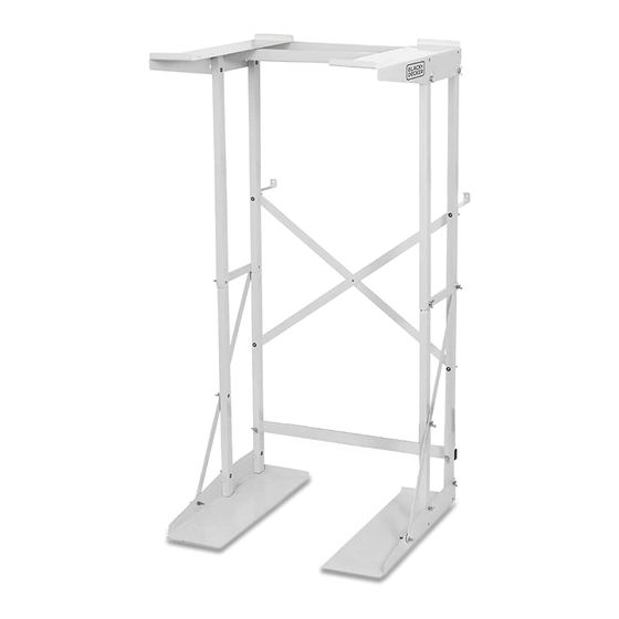
WASHER DRYER STAND
INSTRUCTION MANUAL
CATALOG NUMBER
BWDS
Thank you for choosing BLACK+DECKER!
PLEASE READ BEFORE RETURNING THIS PRODUCT FOR ANY
REASON.
If you have a question or experience a problem with your BLACK+DECKER
purchase, go to www.blackanddecker.com/instantanswers
If you can't find the answer or do not have access to the Internet, call
844-299-0879 from 10:30 a.m. to 6:30 p.m. EST Mon.-Fri. to speak with an
agent. Please have the catalog number available when you call.
SAVE THIS MANUAL FOR FUTURE REFERENCE.
Page 1
Advertisement
Chapters
Table of Contents

Related Manuals for Black & Decker BWDS


Summary of Contents for Black & Decker BWDS
- Page 1 WASHER DRYER STAND INSTRUCTION MANUAL CATALOG NUMBER BWDS Thank you for choosing BLACK+DECKER! PLEASE READ BEFORE RETURNING THIS PRODUCT FOR ANY REASON. If you have a question or experience a problem with your BLACK+DECKER purchase, go to www.blackanddecker.com/instantanswers If you can’t find the answer or do not have access to the Internet, call 844-299-0879 from 10:30 a.m.
-
Page 2: Table Of Contents
CONTENTS SAFETY INFORMATION Important Safety Instructions .............................. 3 SET UP & USE Parts List ....................................4-6 Assembly Instructions ............................7-17 CLEANING & CARE ..............................18 TROUBLESHOOTING & WARRANTY Important ...................................18 Limited Warranty ..................................19 PRODUCT REGISTRATION Thank you for purchasing our BLACK+DECKER product. This Model number easy-to-use manual will guide you in getting the best use of your... -
Page 3: Safety Information
SAFETY INFORMATION DANGER WARNING CAUTION DANGER - Immediate hazards WARNING - Hazards or unsafe CAUTION - Hazards or unsafe that WILL result in severe practices that COULD result in practices that COULD result in personal injury or death severe personal injury or death minor personal injury IMPORTANT SAFETY INSTRUCTIONS WARNING... -
Page 4: Set Up & Use
SET UP & USE PARTS LIST Tools Required: Screwdriver and Drill. NOTE: 15S = 2 short butterfly screws. Used for installing Support Rails, to L-BP and R-BP pieces. Must be inserted so that wing is on exterior side of unit. 25S = 14 short butterfly screws. - Page 5 SET UP & USE L-BP R-BP R-BP L-BP Connecting Rail RB2-2 LF1-1 RF1-1 LB2-2 Diagonal Support Rail LB2-1 RB2-1 LF1-2 RF1-2 Reinforcing Bar Support Rail Non-slip Pad Anti-tip Bracket Lag Type Screws Page 5...
- Page 6 SET UP & USE DESCRIPTION QUANTITY LEFT DRYER SUPPORT L-BP RIGHT DRYER SUPPORT R-BP NON-SLIP PAD LEFT BASE PLATE L-BP RIGHT BASE PLATE R-BP UPPER LEFT FRONT VERTICAL POLE LF1-1 UPPER RIGHT FRONT VERTICAL POLE RF1-1 UPPER LEFT BACK VERTICAL POLE LB2-1 UPPER RIGHT BACK VERTICAL POLE RB2-1...
-
Page 7: Assembly Instructions
SET UP & USE ASSEMBLY INSTRUCTIONS 1. Using the diagram below as reference to position the poles, INSERT LB2-2 (LOWER LEFT BACK VERTICAL POLE) and LF1-2 (LOWER LEFT FRONT VERTICAL POLE) into L-BP LEFT BASE. The base of the poles should be positioned between the L-BP slots and aligned with the holes. - Page 8 SET UP & USE Line up the holes of one side of a SUPPORT RAIL, then the CONNECTING RAIL with the holes on the exterior side of LF1-1 (UPPER LEFT FRONT VERTICAL POLE) and LB2-1 (UPPER LEFT BACK VERTICAL POLE). Secure with 25S (BUTTERFLY SCREW).
- Page 9 SET UP & USE 3. Attach REINFORCING BARS to the top and bottom of the left BACK pole and the top of the LF1-1 as shown below. Attach one side of a REINFORCING BAR to LB2-1 . Align the holes and Insert 45L (BUTTERFLY SCREW) through LB2-1 first and then through the reinforcing bar.
- Page 10 SET UP & USE Follow the same steps to assemble the right side: Attach another side of a REINFORCING BAR to RB2-1 . Align the holes and Insert 45L (BUTTERFLY SCREW) through RB2-1 first and then through the reinforcing bar. Attach another side of a REINFORCING BAR to RF1-1 .
- Page 11 SET UP & USE 4. Align L-BP (LEFT DRYER SUPPORT) and insert into LF1-1 (UPPER LEFT FRONT VERTICAL POLE) and LB2-1 (UPPER LEFT BACK VERTICAL POLE). Use 25S screws to secure poles onto support. Make sure 25S screws are inserted with the butterfly wing on the exterior side of the unit.
- Page 12 SET UP & USE 5. Align the holes in the DIAGONAL SUPPORT RAIL, LB2-1 (UPPER LEFT BACK VERTICAL POLE) and ANTI-TIP BRACKET as shown below. Insert 35M (BUTTERFLY SCREW) into the ANTI-TIP BRACKET and insert all the way through the DIAGONAL SUPPORT RAIL and LB2-1 (UPPER LEFT BACK VERTICAL POLE).
- Page 13 SET UP & USE 6. Align the holes on the bottom of the DIAGONAL SUPPORT RAIL and LB2-2 (LOWER LEFT BACK VERTICAL POLE) as shown below. Insert 35M (BUTTERFLY SCREW) through the DIAGONAL SUPPORT RAIL and LB2-2 (LOWER LEFT BACK VERTICAL POLE). Align the holes on the bottom of the DIAGONAL SUPPORT RAIL and RB2-2 (LOWER RIGHT BACK VERTICAL POLE) as shown below.
- Page 14 SET UP & USE 7. Tighten all the BUTTERFLY SCREWS and move the stand to where you intend to attach it to the wall. 8. Mark the position on the wall where the holes of the ANTI-TIP BRACKET will connect to the wall. WARNING: To reduce the likelihood of injury or property damage, the anti tip feature must be properly installed and utilized.
- Page 15 SET UP & USE 9. Place NON-SLIP PADS on the base of the dryer as illustrated below. Make sure to place NON-SLIP PADS where they will rest on the Dryer Rack to avoid slipping. BOTTOM VIEW OF DRYER NON-SLIP PAD NON-SLIP PAD Remove the feet on the bottom of the dryer.
- Page 16 SET UP & USE For Black + Decker dryer models BCED27 and BCED37 position the dryer so the holes of the dryer from the feet are aligned with the back holes of the top of the R-BP dryer rack L-BP (LEFT DRYER SUPPORT) and (RIGHT DRYER SUPPORT).
- Page 17 SET UP & USE 10. Place the washer so the legs sit on L-BP LEFT BASE and R-BP RIGHT BASE. Page 17...
-
Page 18: Cleaning & Care
CLEANING & CARE CLEANING AND MAINTENANCE Use water or a mild soap and water solution to clean your washer dryer stand. Do not use abrasive cleaners which may scratch the surface. TROUBLESHOOTING & WARRANTY IMPORTANT DO NOT RETURN THIS PRODUCT TO THE STORE If you have a problem with this product, please contact the BLACK+DECKER Customer Satisfaction Center at 844-299-0879 or service@appliance.com. -
Page 19: Limited Warranty
TROUBLESHOOTING & WARRANTY LIMITED WARRANTY Any repair, replacement, or warranty service, REPAIR OR REPLACEMENT AS PROVIDED UNDER THIS WARRANTY IS THE EXCLUSIVE REMEDY OF and all questions about this product should be THE CUSTOMER; W APPLIANCE. SHALL NOT BE directed to W Appliance Co. at 844-299-0879 LIABLE FOR ANY INCIDENTAL OR CONSEQUENTIAL from the USA or Puerto Rico. - Page 20 Fits Portable Dryers Maximum Weight of 60 lbs. 21.4” 24.6” total width 50.8” total height Total installed 4” dimensions Width 24.6” Depth 25.7” Height 50.8” 48.8” maximum washer height 21.5” 22.7” 21.7” maximum total depth washer width WARNING: This washer dryer stand is suitable for BLACK+DECKER portable dryers BCED26 and BCED37.
- Page 21 BLACK & DECKER, BLACK+DECKER, the BLACK & DECKER and BLACK+DECKER logos and product names and the orange and black color scheme are trademarks of The Black & Decker Corporation, used under license. All rights reserved. Product in this box may differ slightly from that pictured. Does not affect function.
- Page 22 SUPPORT LAVEUSE-SÉCHEUSE MANUEL D’INSTRUCTIONS NUMÉRO DE CATALOGUE BWDS Merci d’avoir choisi BLACK+DECKER! VEUILLEZ LIRE AVANT DE RETOURNER CE PRODUIT POUR UNE RAISON QUELCONQUE. Si vous avez une question ou rencontrez un problème avec votre achat BLACK+DECKER, allez sur www.blackanddecker.com/instantanswers Si vous ne trouvez pas la réponse ou n’avez pas accès à l’Internet, appelez au 844-299-0879 de 10 h 30 à...
- Page 23 TABLE DES MATIÈRES INFORMATION DE SÉCURITÉ Consignes De Sécurité Importantes ..........................24 CONFIGURATION ET UTILISATION Liste Des Pièces .................................25-27 Instructions De Montage ..........................28-38 NETTOYAGE ET ENTRETIEN ....................... 39 DÉPANNAGE ET GARANTIE Important ..................................39 Garantie Limitée ..................................40 ENREGISTREMENT DU PRODUIT Merci d’avoir acheté...
-
Page 24: Information De Sécurité
INFORMATION DE SÉCURITÉ DANGER ATTENTION AVERTISSEMENT AVERTISSEMENT - Les dangers ATTENTION - Les dangers DANGER - Les dangers immédiats ou pratiques dangereuses qui ou pratiques dangereuses qui qui VONT entraîner des blessures PEUVENT entraîner des blessures PEUVENT entraîner des blessures graves ou la mort graves ou la mort corporelles mineures... -
Page 25: Configuration Et Utilisation
CONFIGURATION ET UTILISATION LISTE DES PIÈCES Outils Requis: Tournevis et Perceuse. NOTE: 15S = 2 vis papillon courtes. Utilisé pour l’installation des Rails De Support, sur les pièces L-BP et R-BP . Doit être inséré de façon à ce que l’aile soit sur le côté extérieur de l’unité. - Page 26 CONFIGURATION ET UTILISATION L-BP L-BP R-BP R-BP Rail De Connexion RB2-2 LF1-1 RF1-1 LB2-2 Rail de support diagonal LB2-1 RB2-1 LF1-2 RF1-2 Barre De Renfort Rail De Support Tampon Antidérapant Support Anti-Basculement Vis De Type Tire-fond Page 26...
- Page 27 CONFIGURATION ET UTILISATION DESCRIPTION QUANTITY SUPPORT DE SÉCHEUSE GAUCHE L-BP SUPPORT DE SÉCHEUSE DROIT R-BP TAMPON ANTIDÉRAPANT PLAQUE DE BASE GAUCHE L-BP PLAQUE DE BASE DROIT R-BP POTEAU VERTICAL AVANT SUPÉRIEUR GAUCHE LF1-1 POTEAU VERTICAL AVANT SUPÉRIEUR DROIT RF1-1 POTEAU VERTICAL ARRIÈRE SUPÉRIEUR GAUCHE LB2-1 POTEAU VERTICAL ARRIÈRE SUPÉRIEUR DROIT RB2-1...
-
Page 28: Instructions De Montage
CONFIGURATION ET UTILISATION INSTRUCTIONS DE MONTAGE 1. En utilisant le schéma ci-dessous comme référence pour positionner les poteaux, INSÉREZ LB2-2 (POTEAU VERTICAL ARRIÈRE INFÉRIEUR GAUCHE) et LF1-2 (POTEAU VERTICAL AVANT INFÉRIEUR GAUCHE) dans L-BP BASE GAUCHE. La base des poteaux doit être positionnée entre les fentes L-BP et aligné avec les trous. - Page 29 CONFIGURATION ET UTILISATION Alignez les trous d’un côté d’un RAIL DE SUPPORT, puis le RAIL DE CONNEXION avec les trous du côté extérieur de LF1-1 (POTEAU VERTICAL AVANT SUPÉRIEUR GAUCHE) et LB2-1 (POTEAU VERTICAL ARRIÈRE SUPÉRIEUR GAUCHE). Fixez avec 25S (VIS PAPILLON). LB2-1 LF1-1 Rail de connexion...
- Page 30 CONFIGURATION ET UTILISATION 3. Fixez les BARRES DE RENFORT en haut et en bas du poteau ARRIÈRE gauche et en haut du LF1-1 comme indiqué ci-dessous. Attachez un côté d’une BARRE DE RENFORT à LB2-1 . Alignez les trous et insérez 45L (VIS PAPILLON) à...
- Page 31 CONFIGURATION ET UTILISATION Suivez les mêmes étapes pour assembler le côté droit: ATTACHEZ UN AUTRE CÔTÉ D’UNE BARRE DE RENFORT À RB2-1 . Alignez les trous et Insérez 45L (VIS PAPILLON) à travers RB2-1 d’abord, puis à travers la barre de renfort.
- Page 32 CONFIGURATION ET UTILISATION 4. Alignez L-BP (SUPPORT DE SÉCHEUSE GAUCHE) et insérez-le dans LF1-1 (POTEAU VERTICAL AVANT SUPÉRIEUR GAUCHE) et LB2-1 (POTEAU VERTICAL ARRIÈRE SUPÉRIEUR GAUCHE). Utilisez des vis 25S pour fixer les poteaux sur le support. Assurez-vous que les vis 25S sont insérées avec l’aile de papillon sur le côté extérieur de l’unité.
- Page 33 CONFIGURATION ET UTILISATION 5. Alignez les trous dans le RAIL DE SUPPORT DIAGONAL, LB2-1 (POTEAU VERTICAL ARRIÈRE SUPÉRIEUR GAUCHE) et SUPPORT ANTI-BASCULEMENT comme indiqué ci-dessous. Insérez 35M (VIS PAPILLON) dans le SUPPORT ANTI-BASCULEMENT et insérez-le complètement à travers le RAIL DE SUPPORT DIAGONAL et LB2-1 (POTEAU VERTICAL ARRIÈRE SUPÉRIEUR GAUCHE).
- Page 34 CONFIGURATION ET UTILISATION 6. Alignez les trous au bas du RAIL DE SUPPORT DIAGONAL et LB2-2 (POTEAU VERTICAL ARRIÈRE INFÉRIEUR GAUCHE) comme indiqué ci-dessous. Insérez 35M (VIS PAPILLON) à travers le RAIL DE SUPPORT DIAGONAL et LB2-2 (POTEAU VERTICAL ARRIÈRE INFÉRIEUR GAUCHE). Alignez les trous au bas du RAIL DE SUPPORT DIAGONAL et RB2-2 (POTEAU VERTICAL ARRIÈRE INFÉRIEUR DROIT) comme indiqué...
- Page 35 CONFIGURATION ET UTILISATION 7. Serrez toutes les VIS PAPILLON et déplacez le support à l’endroit où vous avez l’intention de le fixer au mur. 8. Marquez la position sur le mur où les trous du SUPPORT ANTI-BASCULEMENT se connecteront au mur. AVERTISSEMENT: Pour réduire les risques de blessures ou dommages matériels, la fonction anti-basculement doit être correctement installée et utilisée.
- Page 36 CONFIGURATION ET UTILISATION 9. Placez des TAMPONS ANTIDÉRAPANTS sur la base de la sécheuse comme illustré ci-dessous. Assurez-vous de placer des TAMPONS ANTIDÉRAPANTS là où ils reposeront sur la grille de la sécheuse pour éviter de glisser. VUE DE DESSOUS DE LA SÉCHEUSE TAMPON TAMPON ANTIDÉRAPANT...
- Page 37 CONFIGURATION ET UTILISATION Pour les modèles de sécheuse Black+Decker BCED27 et BCED37, positionnez la sécheuse de sorte que les trous de la sécheuse des pieds soient alignés avec les trous arrière du haut de la grille de la sécheuse L-BP (SUPPORT DE SÉCHEUSE GAUCHE) et R-BP (SUPPORT DE SÉCHEUSE DROIT).
- Page 38 CONFIGURATION ET UTILISATION 10. Placez la laveuse de sorte que les pieds reposent sur L-BP BASE GAUCHE et R-BP BASE DROITE. Page 38...
-
Page 39: Nettoyage Et Entretien
NETTOYAGE ET ENTRETIEN NETTOYAGE ET MAINTENANCE Utilisez de l’eau ou une solution d’eau et de savon doux pour nettoyer votre support de laveuse sécheuse. N’utilisez pas de nettoyants abrasifs qui pourraient rayer la surface. DÉPANNAGE ET GARANTIE IMPORTANT NE PAS RETOURNER CE PRODUIT AU MAGASIN Si vous rencontrez un problème avec ce produit, veuillez contacter le Centre de Satisfaction Client BLACK+DECKER au 844-299-0879 ou service@appliance.com. -
Page 40: Garantie Limitée
DÉPANNAGE ET GARANTIE GARANTIE LIMITÉE Toute réparation, remplacement ou service de LA RÉPARATION OU LE REMPLACEMENT TEL QUE FOURNI DANS LE CADRE DE CETTE GARANTIE EST garantie, et toutes les questions sur ce produit LE RECOURS EXCLUSIF DU CLIENT; W Appliance doivent être adressées à... - Page 41 Convient aux Sécheuses Portatives Poids Maximum de 60 lb. 21.4” 24.6” largeur totale 50.8” hauteur totale Dimensions totales 4” installées Largeur 24.6” Profondeur 25.7” Hauteur 50.8” 48.8” Hauteur maximale de la machine à laver 21.5” 21.7” 22.7” Largeur profondeur maximale de la totale machine à...
- Page 42 BLACK & DECKER, BLACK+DECKER, les logos et noms de produits BLACK & DECKER et BLACK+DECKER ainsi que le schéma de couleurs orange et noir sont des marques déposées de The Black & Decker Corporation, utilisées sous licence. Tous droits réservés. Le produit dans cette boîte peut différer légèrement de celui illustré.
- Page 43 SOPORTE DE SECADORA PARA LAVADORA MANUAL DE INSTRUCCIONES NÚMERO DE CATÁLOGO BWDS ¡Gracias por elegir BLACK+DECKER! POR FAVOR, LEA ESTE MANUAL ANTES DE DEVOLVER ESTE PRODUCTO POR CUALQUIER MOTIVO. Si tiene una pregunta o sufre un problema con su compra de BLACK+DECKER, diríjase a www.blackanddecker.com/instantanswers...
- Page 44 CONTENIDO INFORMACIÓN DE SEGURIDAD Instrucciones importantes de seguridad ........................45 CONFIGURACIÓN Y USO Lista de piezas ...................................46-48 Instrucciones de montaje ..........................49-59 LIMPIEZA Y CUIDADO ..........................60 RESOLUCIÓN DE PROBLEMAS Y GARANTÍA Importante ................................60 Garantía limitada ..................................61 REGISTRO DEL PRODUCTO Gracias por comprar nuestro producto BLACK+DECKER.
-
Page 45: Información De Seguridad
INFORMACIÓN DE SEGURIDAD PELIGRO ADVERTENCIA PRECAUCIÓN ADVERTENCIA - Peligros o PELIGRO - Amenazas inmediatas PRECAUCIÓN - Peligros o prácticas prácticas inseguras que pueden que resultarán en lesiones inseguras que podrían resultar en resultar en lesiones personales personales graves o la muerte lesiones personales menores graves o la muerte INSTRUCCIONES IMPORTANTES DE SEGURIDAD... -
Page 46: Configuración Y Uso
CONFIGURACIÓN Y USO LISTA DE PIEZAS Herramientas necesarias: destornillador y taladro. NOTA: 15S = 2 tornillos de mariposa cortos. Se usan para instalar los rieles de soporte para las piezas L-BP y R-BP pieces. Debe insertarse de manera que el ala esté en el lado exterior de la unidad. - Page 47 CONFIGURACIÓN Y USO L-BP R-BP L-BP R-BP Riel de conexión RB2-2 LF1-1 RF1-1 LB2-2 Riel de soporte diagonal LB2-1 RB2-1 LF1-2 RF1-2 Barra de refuerzo Riel de soporte Almohadilla antideslizante Anclaje anti-vuelco Tornillos tipo tirafondos Page 47...
- Page 48 CONFIGURACIÓN Y USO DESCRIPTION QUANTITY SOPORTE DE SECADORA IZQUIERDO L-BP SOPORTE DE SECADORA DERECHO R-BP ALMOHADILLA ANTIDESLIZANTE PLACA BASE IZQUIERDA L-BP PLACA BASE DERECHA R-BP LF1-1 POSTE VERTICAL SUPERIOR IZQUIERDO DELANTERO RF1-1 POSTE VERTICAL SUPERIOR DERECHO DELANTERO LB2-1 POSTE VERTICAL SUPERIOR IZQUIERDO TRASERO RB2-1 POSTE VERTICAL SUPERIOR DERECHO TRASERO LB2-2...
-
Page 49: Instrucciones De Montaje
CONFIGURACIÓN Y USO INSTRUCCIONES DE MONTAJE 1. Con el diagrama siguiente como referencia para colocar los postes, INSERTE LB2-2 (POSTE VERTICAL INFERIOR IZQUIERDO TRASERO) y LF1-2 (POSTE VERTICAL INFERIOR IZQUIERDO FRONTAL) en L-BP BASE IZQUIERDA. La base de los postes debería estar entre las ranuras de L-BP y alineada con los orificios. - Page 50 CONFIGURACIÓN Y USO Alinear los orificios de un lado de un RIEL DE SOPORTE, luego el RIEL DE CONEXIÓN con los orificios del exterior de LF1-1 (POSTE VERTICAL SUPERIOR IZQUIERDO DELANTERO) y LB2-1 (POSTE VERTICAL SUPERIOR IZQUIERDO TRASERO). Use 25S (TORNILLOS MARIPOSA). LB2-1 LF1-1 Carril de conexión...
- Page 51 CONFIGURACIÓN Y USO 3. Fije las BARRAS DE REFUERZO en las partes superior e inferior del poste TRASERO y la parte superior de LF1-1 como se muestra a continuación. Fije un lado de una BARRA DE REFUERZO a LB2-1 . Alinear los orificios e insertar un 45L (TORNILLO MARIPOSA) primero a través de LB2-1 y luego a través de la barra de refuerzo.
- Page 52 CONFIGURACIÓN Y USO Siga los mismos pasos para montar el lado derecho: Fije un lado de una BARRA DE REFUERZO a RB2-1 . Alinear los orificios e insertar un 45L (TORNILLO MARIPOSA) primero a través de RB2-1 y luego a través de la barra de refuerzo.
- Page 53 CONFIGURACIÓN Y USO 4. Alinear L-BP (SOPORTE IZQUIERDO) e insertar en LF1-1 (POSTE VERTICAL SUPERIOR IZQUIERDO FRONTAL) y LB2-1 (POSTE VERTICAL SUPERIOR IZQUIERDO TRASERO). Use los tornillos 25S para asegurar los postes al soporte. Asegúrese de que los tornillos 25S estén insertados de forma que las alas de la tuerca de mariposa queden hacia el exterior de la unidad.
- Page 54 CONFIGURACIÓN Y USO 5. Alinear los orificios en el RIEL DE SOPORTE DIAGONAL, LB2-1 (POSTE VERTICAL SUPERIOR IZQUIERDO TRASERO) y el SOPORTE ANTIVUELCO como se muestra a continuación. Inserte tornillos 35M (TORNILLO MARIPOSA) en el SOPORTE ANTIVUELCO completamente a través del RIEL DE SOPORTE DIAGONAL y LB2-1 (POSTE VERTICAL SUPERIOR IZQUIERDO TRASERO).
- Page 55 CONFIGURACIÓN Y USO 6. Alinear los orificios en la parte inferior del RIEL DE SOPORTE DIAGONAL y LB2-2 (POSTE VERTICAL INFERIOR IZQUIERDO TRASERO) como se muestra a continuación. Inserte tornillos 35M (TORNILLO MARIPOSA) a través del RIEL DE SOPORTE DIAGONAL y LB2-2 (POSTE VERTICAL INFERIOR IZQUIERDO TRASERO).
- Page 56 CONFIGURACIÓN Y USO 7. Apriete todos los TORNILLOS MARIPOSA y mueva el soporte a donde desee amurarlo a la pared. 8. Marque en la pared la posición donde irán los SOPORTES ANTIVUELCO. ADVERTENCIA: Para reducir la probabilidad de lesiones o daños a la propiedad, la función antivuelco debe instalarse y utilizarse correctamente.
- Page 57 CONFIGURACIÓN Y USO 9. Coloque ALMOHADILLAS ANTIDESLIZANTES en la base de la secadora como se ilustra a continuación. Asegúrese de colocar ALMOHADILLAS ANTIDESLIZANTES en las zonas de apoyo del estante de secadora/lavadora para evitar deslizamientos. VISTA INFERIOR DE LA SECADORA ALMOHADILLA ANTIDESLIZANTE ALMOHADILLA...
- Page 58 CONFIGURACIÓN Y USO Para los modelos de secadora de Black + Decker BCED27 y BCED37, coloque la secadora de modo que los orificios de las patas de la secadora estén alineados con los orificios traseros del soporte L-BP (SOPORTE IZQUIERDO) y R-BP (SOPORTE DERECHO).
- Page 59 CONFIGURACIÓN Y USO 10. Coloque la lavadora para que las patas se apoyen en L-BP BASE IZQUIERDA y R-BP BASE DERECHA. Page 59...
-
Page 60: Limpieza Y Cuidado
LIMPIEZA Y CUIDADO LIMPIEZA Y MANTENIMIENTO Use agua o una solución de agua y jabón suave para limpiar su soporte de secadora/ lavadora. No utilice limpiadores abrasivos que podrían rayar la superficie. RESOLUCIÓN DE PROBLEMAS Y GARANTÍA IMPORTANTE NO DEVUELVA ESTE PRODUCTO A LA TIENDA Si tiene un problema con este producto, comuníquese con el Centro de Satisfacción del Cliente de BLACK+DECKER al 844- 299-0879 o service@equitybrands.com. -
Page 61: Garantía Limitada
TROUBLESHOOTING & WARRANTY LIMITED WARRANTY Any repair, replacement, or warranty service, REPAIR OR REPLACEMENT AS PROVIDED UNDER THIS WARRANTY IS THE EXCLUSIVE REMEDY OF and all questions about this product should be THE CUSTOMER; W APPLIANCE. SHALL NOT BE directed to W Appliance Co. at 844-299-0879 LIABLE FOR ANY INCIDENTAL OR CONSEQUENTIAL from the USA or Puerto Rico. - Page 62 21.4” 24.6” ancho total 50.8” altura total Dimensiones totales 4” una vez instalado: Ancho 24,6”, Profundidad 25,7”, Altura 50,8” 48.8” altura máxima de la lavadora 21.5” 21.7” 22.7” ancho máximo profundidad de la lavadora total ADVERTENCIA: Este soporte para lavadora/secadora es adecuado para las secadoras portátiles BCED26 y BCED37 de BLACK + DECKER.
- Page 63 BLACK & DECKER, BLACK+DECKER, y los logos y nombres de productos de BLACK & DECKER y BLACK + DECKER, los logotipos y nombres de productos y el esquema de color naranja y negro son marcas comerciales de The Black & Decker Corporation, utilizados bajo licencia.