Table of Contents
Advertisement
Quick Links
Federal Communications Commission (FCC) Statement
This equipment has been tested and found to comply with the limits for a Class B digital
device, pursuant to Part 15 of FCC Rules. These limits are designed to provide reasonable
protection against harmful interference in a residential installation. This equipment
generates, uses and can radiate radio frequency energy and, if not installed and used in
accordance with instructions contained in this manual, may cause harmful interference
to radio and television communications. However, there is no guarantee that interference
will not occur in a particular installation.
If this equipment does cause harmful interference to radio or television reception, which
can be determined by turning the equipment off and on, the user is encouraged to try to
correct the interference by one or more of the following measures:
- REORIENT OR RELOCATE THE RECEIVING ANTENNA
- INCREASE THE SEPARATION BETWEEN THE EQUIPMENT AND THE RECEIVER
- CONNECT THE EQUIPMENT INTO AN OUTLET ON A CIRCUIT DIFFERENT FROM
THAT OF THE RECEIVER
- CONSULT THE DEALER OR AN EXPERIENCED AUDIO/TELEVISION TECHNICIAN
NOTE: Connecting this device to peripheral devices that do not comply with Class B
requirements, or using an unshielded peripheral data cable, could also result in
harmful interference to radio or television reception.
The user is cautioned that any changes or modifications not expressly approved
by the party responsible for compliance could void the user's authority to operate
this equipment.
To ensure that the use of this product does not contribute to interference, it is
necessary to use shielded I/O cables.
Copyright
This manual is copyrighted with all rights reserved. No portion of this manual may be
copied or reproduced by any means.
While every precaution has been taken in the preparation of this manual, no responsibility
for errors or omissions is assumed. Neither is any liability assumed for damages resulting
from the use of the information contained herein.
Trademarks
All brand names, logos and registered trademarks mentioned are property of their
respective owners.
Electronic Emission Notices
Advertisement
Table of Contents

Related Manuals for Gigabyte AMD785G


Summary of Contents for Gigabyte AMD785G
- Page 1 Electronic Emission Notices Federal Communications Commission (FCC) Statement This equipment has been tested and found to comply with the limits for a Class B digital device, pursuant to Part 15 of FCC Rules. These limits are designed to provide reasonable protection against harmful interference in a residential installation.
- Page 2 Safety Environmental Instruction Avoid the dusty, humidity and temperature extremes. Do not place the product in any area where it may become wet. 0 to 40 centigrade is the suitable temperature. (The figure comes from the request of the main chipset) ...
-
Page 3: Features Of Motherboard
Introduction Features of motherboard The AMD785G chipset motherboard series are based on the latest AMD785G Chipset and the SB710 chipset which supports the following AM3 CPU in the 95W range: Phenom II x 4;Phenom II x 3;Phenom II x2;Athlon II x4;Athlon II x3;Athlon II x2;... - Page 4 descriptions of these value added product features, please get them in the coming section. Special Features of Motherboard CPU Thermal Throttling Technology---(The CPU Overheat Protection Technology) To prevent the increasing heat from damage of CPU or accidental shutdown while at high workload, the CPU Thermal Throttling Technology will force CPU to enter partially idle mode from 87.5% to 12.5% according to preset CPU operating temperature in BIOS (from 40℃...
-
Page 5: Specification
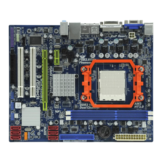
Spec Description Design Micro ATX form factor; size:24.5cm*21.0cm AMD785G North Bridge Chipset Chipset AMD SB710 South Bridge Chipset Phenom II x 4 ; Phenom II x 3 ; Phenom II x2 ; Athlon II x4 ; ... - Page 6 Layout Diagram & Jumpers Setting Line-IN VGA Connector RJ-45 LAN HDMI Connector Line-OUT PS/2 Mouse PS/2 Keyboard MIC-IN DVI Connector SPDIF_OUT Connector USB Connector KBMB/USB Power On(JP1) CPUFAN ATX 12V Power Connector PS2 KB/MS Port Power-saving LED SPDIF_OUT DDRIII Slot x 2 Connector HDMI Connector ATX Power Conn.
-
Page 7: Hardware Installation Steps
Hardware Installation WARNING! Turn off your power when adding or removing expansion cards or other system components. Failure to do so may cause severe damage to both your motherboard and expansion cards. Hardware installation Steps Before using your computer, you had better complete the following steps: 1. -
Page 8: Install Cpu
3. After over clocking system boot fail J B A T J B A T 1-2 C l o s e d N o r m a l 2-3 C l o s e d C l e a r C M O S C M O S R A M C l e a r S e t t i n g Install CPU About AMD AM3 CPU Installation... -
Page 9: Install Memory
Install Memory This motherboard provides two 240-pin DDRIII DUAL INLINE MEMORY MODULES (DIMM) socket for DDRIII memory expansion to maximum memory volume of 8 GB DDR SDRAM. Valid Memory Configurations Bank 240-Pin DIMM PCS Maximum Capacity DDRIII1 DDRIII800/DDRIII1066/DDRIII1333/ DDRIII2 DDRIII800/DDRIII1066/DDRIII1333/ Total System Memory (Max 4 GB) :... -
Page 10: Expansion Cards
Expansion Cards Procedure For Expansion Card Installation 1. Read the documentation for your expansion card and make any necessary hardware or software setting for your expansion card such as jumpers. 2. Remove your computer’s cover and the bracket plate on the slot you intend to use. 3. -
Page 11: Connectors, Headers
PCI-E x16 Slotby16-lane 32-bit PCI Slot Connectors, Headers Connectors Power Connector (24-pin block): ATXPWR1 ATX Power Supply connector: This is a new defined 24-pins connector that usually comes with ATX case. The ATX Power Supply allows using soft power on momentary switch that connect from the front panel switch to 2-pins Power On jumper pole on the motherboard. - Page 12 ROW1 ROW2 ROW1 ROW2 ROW1 ROW2 3.3V 3.3V 3.3V -12V Soft Power On Power OK +5V (for Soft Logic) +12V +12V Pin 1 Pin 1 24-Pin 20-Pin (2)ATX 12V Power Connector (8-pin block) : ATX12V This is a new defined 8-pins connector that usually comes with ATX Power Supply.
- Page 13 Line-IN RJ-45 LAN PS/2 Mouse Line-OUT SPDIF_OUT HDMI MIC-IN PS/2 Keyboard USB Connectors (7) Primary IDE Connector (40-pin block): IDE1 This connector supports the provided IDE hard disk ribbon cable. After connecting the single plug end to motherboard, connect the two plugs at other end to your hard disk(s).
- Page 14 (9) D-Sub 15-pin Connector: VGA VGA connector is the 15-pin D-subminiature female connector; it is for the display devices, such as the CRT monitor, LCD monitor and so on. (10) Digital Visual Interface: DVI1 This interface standard designed to maximize the visual quality of digital display devices such as flat panel LCD computer displays and digital projectors.
- Page 15 (3) Speaker connector: SPEAK1 This 4-pin connector connects to the case-mounted speaker. See the figure below. (4) Power LED: PWR LED/PWRLED1 The Power LED is light on while the system power is on. Connect the Power LED from the system case to this pin. (5) IDE Activity LED: HD LED This connector connects to the hard disk activity indicator light on the case.
- Page 16 (9) CD Audio-In Headers (4-pin): CDIN1 CDIN are the connectors for CD-Audio Input signal. Please connect it to CD-ROM CD-Audio output connector. CDIN CD Audio-In Headers (10) Serial COM Port header: COM1 COM1 is the 9-pin block pin-header. P i n 1 S e r i a l C O M P o r t 9 -p i n B l o c k (11) HDMI-SPDIF Out header: SPDIF Out...
-
Page 17: Starting Up Your Computer
Starting Up Your Computer 1. After all connection are made, close your computer case cover. 2. Be sure all the switch are off, and check that the power supply input voltage is set to proper position, usually in-put voltage is 220V240V or 110V120V depending on your country’s voltage used. -
Page 18: Introducing Bios
Introducing BIOS The BIOS is a program located on a Flash Memory on the motherboard. This program is a bridge between motherboard and operating system. When you start the computer, the BIOS program will gain control. The BIOS first operates an auto-diagnostic test called POST (power on self test) for all the necessary hardware, it detects the entire hardware device and configures the parameters of the hardware synchronization. - Page 19 AMI Once you enter BIOS CMOS Setup Utility, the Main Menu (Figure 3-1) will appear on the screen. The Main Menu allows you to select from fourteen setup functions and two exit choices. Use arrow keys to select among the items and press <Enter>...
-
Page 20: Standard Bios Features
Use this menu to set supervisor password and user password. Load Standard Defaults This menu uses a minimal performance setting, but the system would run in a stable way. Load Optimal Defaults Use this menu to load the BIOS default values these are setting for optimal performances system operations for performance use. -
Page 21: Advanced Bios Features
While entering setup, BIOS auto detest the presence of IDE devices. This displays the status of auto detection of IDE devices. Type: The optional settings are: Not Installed; Auto; CD/DVD and ARMD LBA/Large Mode: The optional settings are Auto; Disabled. Disabled: Disables LBA Mode. -
Page 22: Cpu Configuration
MPS Revision This option is only valid for multiprocessor motherboards as it specifies the version of the Multiprocessor Specification (MPS) that the motherboard will use. Quiet Boot The optional settings are Enabled and Disable. Disabled: Display normal POST message. Enabled: Displays OME logo instead of POST message. CPU Configuration CMOS Setup Utility-Copyright(C)1985-2005 American Megatrends. -
Page 23: Memory Configuration
HDMI Audio Use this item to select HDMI audio, the optional settings are: Disabled and Enabled. Default is Enabled. Primary Video Controller This item is for user to choose primary video controller. Memory Configuration CMOS Setup Utility-Copyright(C)1985-2005 American Megatrends. Inc. Memory Configuration Help Item DRAM Timing Mode... -
Page 24: Pci Express Configuration
Internal Graphics Configurations CMOS Setup Utility-Copyright(C)1985-2005 American Megatrends. Inc. Internal Graphics Configurations Internal Graphics Mode UMA+SIDEPORT Help Item UMA Frame Buffer Size Auto Options SIDEPORT Clock Speed 667MHz Disabled GFX Engine Clock Override Disabled SIDEPORT UMA-SP Interleave Mode Auto UMA+SIDEPORT SP Power Management Auto SP NB Termination... -
Page 25: Integrated Peripherals
Integrated Peripherals CMOS Setup Utility-Copyright(C)1985-2005 American Megatrends. Inc. Integrated Peripherals Onboard SATA Device Press Enter Onboard Device Control Press Enter Help Item Super IO Configuration Press Enter : Move Enter: Select +/-/: Value F10: Save ESC: Exit F1: General Help F5: Discard Charges F6: Standard Defaults F7: Optimized Defaults... -
Page 26: Super Io Configuration
Super IO Configuration CMOS Setup Utility-Copyright(C)1985-2005 American Megatrends. Inc. Super IO Configuration Help Item Configure F71863 Super IO Chipset Allows BIOS to Enable or Disable Power On By Keyboard Disabled Floppy Controller Power On By Mouse Disabled Serial Port 1 Address 3F8/IRQ4 Serial Port 2 Address 2F8/IRQ3... -
Page 27: Miscellaneous Control
CMOS Setup Utility-Copyright(C)1985-2005 American Megatrends. Inc. Power Management Setup Power Management Feature Help Item Power management/APM Enabled Suspend Time Out Disabled Power Button Mode On/Off Disable/Enable Video Power Down Mode Suspend RTC to generate a wake event Hard Disk Power Down MODE Suspend Hard Disk Time Out (Minute) Disabled... -
Page 28: Pc Health Status
Yes: Assigns IRQ to PCI VGA card if card requests IRQ. No: Does not assign IRQ to PCI VGA card even card requests an IRQ. Palette Snooping The optional settings are: Enabled; Disabled. Enable: inform the PCI device that an ISA graphics devices is installed in the system so the card will function correctly. -
Page 29: Thermal Throttling Options
Smart FAN Configurations FAN1 Mode Setting The optional settings are: Auto Fan by RPM; Auto Fan by Dutycycle; Manual Mode by RPM and Manual Mode by Dutycycle. Thermal Throttling Options CMOS Setup Utility-Copyright(C)1985-2005 American Megatrends. Inc. Thermal Throttling Options Help Item CPU Thermal-Throttling Enabled Options... -
Page 30: Bios Security Features
PCI E Reference Clock The enabled setting is 100. SB Reference Clock The enabled setting is 100. Processor Voltage The optional settings are: Auto; 0.800V~1.350V. AOD Compatibility Choose Enabled means only AMD over drive can adjust voltage Choose Disabled means only BIOS can adjust voltage Memory Clock Mode The optional settings are: Auto;... - Page 31 Save Changes and Exit / Discard and Exit Save Changes and Exit When you press <Enter> on this item, you get a confirmation dialog box with a message similar to: Save Configuration changes and exit setup? 【OK】 【Cancel】 Pressing <OK> save the values you made previously and exit BIOS setup. Discard Changes and Exit When you press <Enter>...
-
Page 32: Driver & Free Program Installation
DRIVER & FREE PROGRAM INSTALLATION Check your package and there is A MAGIC INSTALL CD included. This CD consists of all DRIVERS you need and some free application programs and utility programs. In addition, this CD also include an auto detect software which can tell you which hardware is installed, and which DRIVERS needed so that your system can function properly. - Page 33 Install ATI Driver Pack 1. Click ATI when the MAGIC INSTALL 2. Click NEXT when ATI software driver pack MENU appears. appears. 3. Click “Yes” to accept the license 4. Click Express, recommended. agreement and start installation.. 5. Click Continue Anyway. 6.
- Page 34 Sound Install HD Codec Audio Driver 1. Click SOUND when MAGIC INSTALL 2. Click NEXT When Realtek High Definition MENU appears Audio driver windows appear 3. Click FINISH and restart your computer 4. Manual Sound Effect Setting 5. Devices and mixer setting 6.
- Page 35 NOTE: Please upgrade your Windows XP to Service Pack 1 / Windows 2000 to Service Pack 4 or later before you the HD Audio CODEC driver. LAN Install Gigabit Ethernet NIC Driver 1 Click LAN when MAGIC INSTALL MENU 2. Click Next . appears 3 Click Install 2.
- Page 36 Norton Install Norton 2009 Anti-virus program 1 Click NORTON when MAGIC INSTALL 2. Please select Agree&install. MENU appears PC-Health Install MyGuard Hardware Monitor Utility 1. Click PC-HEALTH when MAGIC INSTALL 2. Click Next on Install shield wizard Window MENU appears appears 3.
- Page 37 HDMI Install ATI HDMI Audio Driver 1. Click HDMI when MAGIC INSTALL 2. Click Next on Install shield wizard MENU appears Window appears 3. Choose finish. OVERCLOCK Install OVERCLOCK Drive Utility 1. Click OVER CLOCK when MAGIC 2. Click Next INSTALL MENU appears...
- Page 38 4. Choose “I accept the terms in the license 3. Read the information, then click next. agreement”. 5. Choose “Anyone who use this computer” 6. The information describe the installation, Click Next. Click Next. 7. Choose Yes and Next. 8. Ready to install the program, click Install. 9.
-
Page 39: How To Update Bios
How to Update BIOS STEP 1. Prepare a boot disc. (You may make one by click START click RUN type SYS A: click OK) STEP 2. Download upgrade tools and the latest BIOS files of the motherboard from official website and then make a copy of it to your bootable floppy disk after decompressing these files STEP 3. - Page 40 [figure3] Press [2] key, the interface of RAID, as figure 4. RAID function: RAID 0/ RAID 1/ RAID 10 [figure4] Choose LD 1 then press Enter. Take Raid0 for example, use [↑] [↓] to shift the cursor, press space key to change the choice, press [Ctrl-Y] to keep.
- Page 41 [figure5] [figure6] Press [3], delete the RAID mode, as figure 7.press [Delete] will delete the array. As figure 7 . [figure7] Press [4], showing the information of controller, as figure 8.
- Page 42 [figure8] Making RAID driver diskette before Install WindowsXP/2000/Vista/Windows7 Before you install the operating system, you will need to make a RAID driver diskette before you start to install the Operating System. How to make a RAID driver diskette? 1: Insert the diskette which is being formatted in floppy drive on a system which can start OS.
-
Page 43: Function Led Display
G.P.I Function LED Display: PP_LED3 Lights off. It means the motherboard in the G.P.I mode. CPU works with the low power consumption. PP_LED3 Lights on. It means that the CPU works with high power consumption. - Page 44 Appendix Debug Port Post Code Normal POST Codes NOTE: EISA POST codes are typically output to port address 300h. ISA POST codes are output to port address 80h. Code(hex) Name Description Turn Off Chipset OEM Specific-Cache control cache And CPU test Processor Status (1FLAGS) Verification.
- Page 45 Blank video Reset Video controller Reserved Init KBC Keyboard controller init KB test Test the Keyboard Reserved Mouse Init Initialized the mouse Onboard Audio init Onboard audio controller initialize if exist Reserved Reserved CheckSum Check Check the intergraty of the ROM,BIOS and message Reserved Auto detec EEPROM...
- Page 46 Reserved PS2 Mouse setup Setup PS2 Mouse and reset KB Reserved Test DMA Controller Test DMA channel 0 Reserved Test DMA Controller Test DMA channel 1 Reserved Test DMA Page Test DMA Page Registers. Registers Reserved Reserved Test Timer Counter 2 Test 8254 Timer 0 Counter 2.
- Page 47 CPU vendor specific version string and turn on all necessary CPU features Reserved PnP Init Display PnP logo and PnP early init Reserved Setup Virus Protect Setup virus protect according to Setup Reserved Awdflash Load If required, will auto load Awdflash.exe in POST Reserved Onboard I/O Init...
-
Page 48: Quick Post Codes
and ask for user intervention Reserved Reserved Security Check Ask password security (optional). Write CMOS Write all CMOS values back to RAM and clear screen. Pre-boot Enable Enable parity checker Enable NMI, Enable cache before boot. Initialize Initialize any option ROMs present Option ROMs from C8000h to EFFFFh. - Page 49 If support HPM, HPM get initialized here KBC and CMOS Init Verifies CMOS is working correctly, detects bad battery. If failed, load CMOS defaults and load into chipset Final Initial KBC and setup BIOS data area. Video Init Read CMOS location 14h to find out type of video in use.
-
Page 50: S4 Post Codes
Enable NMI, Enable cache before boot. Initialize any option ROMs present from C8000h to EFFFFh. NOTE: When FSCAN option is enabled, ROMs initialize from C8000h to F7FFFh. Reserved Reserved Reserved Reserved Boot Medium Read and store boot partition head and detection cylinders values in RAM Final Init... -
Page 51: Bootblock Post Codes
Detect and Initialize Video Adapter. Video memory test Test video memory, write sign-on message to screen. Setup shadow RAM - Enable shadow according to Setup. Setup PS2 mouse and Setup PS2 Mouse and reset KB test DMA Test DMA channel 0 Test 8259 Test 8259 channel 1 and mask IRQ 9 Init Boot Device... - Page 52 Suggestion on choosing electric fan Both the amount of electric current to MOSFET and the heat produced from the motherboard go up as AMD’s CPU power consumption increases. In this case we recommend users select a CPU fan with air outlet towards MOSFET so that CPU fan can carry away heat produced by MOSFET, for better heat dissipation effects.
- Page 53 Glossary Chipset (or core logic) - two or more integrated circuits which control the interfaces between the system processor, RAM, I/O devises, and adapter cards. Processor socket - the socket used to mount the system processor on the motherboard. Slot (PCI-E, PCI, RAM) - the slots used to mount adapter cards and system RAM. PCI - Peripheral Component Interconnect - a high speed interface for video cards, sound cards, network interface cards, and modems;...